I just want to highlight one matter. Amps like this generally don't have a true analog input. Typically the input is routed into the Bluetooth chip and then digitized and then goes through a D to A again.Hi,
I was interested in the MA12070 PCB, but wanted to try before the MA12040 which is already in a box and with a Qualcomm QCC3003 bluetooth chip (not the best but handy in my workshop). So I bought from Douk and the delivery was quick. The amplifier is very quiet and no pop when opening.
Mini Bluetooth 5.0 Digital Amplifier Stereo Receiver 2.0 Channel Car Speaker Amp | eBay
From the power on I liked the sound. I prefer it to my stock 3eaudio TPA3251 (not modified), more dynamic and lively, more definition. Currently I have a SMPS of 12vdc 2.7A, not great but I have several transformers and PSUs, I will put 17-18vdc max. With 12vdc, in 4ohms it is 13w / c and in my living room at normal listening power, it does not lack power. I am very amazed and even shocked at the sound quality and the tonal balance versus the price it costs. I will surely buy the MA12070 PCB and try it too.
That's how they implement the auto input select for such inputs. It is done inside the bluetooth chip.
So there might be additional "colour" from that process.
Best to use a board and build your own amp if using analog inputs.
Oon
I disagree with your opinion.
Normally, in an amplifier that operates by switching between BT and analog input like this amplifier, the external relay unit is operated by the connection establishment signal from the BT unit, and the two analog signals of BT and AUX are switched.
It is not an operation that AD-converts the AUX analog signal you say and inputs it to the BT unit.
Last edited:
Might be true if amp is based on the i2s variant of the MA chip. But then you wouldn't have to go back to analog.
//
//
Last edited:
Well, I can't say for this amp specifically, but the amplifier board from sure electronics and tinysine does this.I disagree with your opinion.
Normally, in an amplifier that operates by switching between BT and analog input like this amplifier, the external relay unit is operated by the connection establishment signal from the BT unit, and the two analog signals of BT and AUX are switched.
It is not an operation that AD-converts the AUX analog signal you say and inputs it to the BT unit.
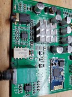
As for your amplifier, I can't be certain but there is a white rectangular component next to the volume control might be a relay, but it looks quite small. I can't see any other signal relays. But I suspect it might be a power relay, the switch on the volume control would not have enough current to handle this, might be used to turn on relay.
Oon

We hear very well on board. By default it's in aux mode, from what I'm seeing here and hearing. I have other PCBs with Qualcomm Bluetooth.
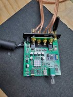
On one of the photos, you can see I soldered the direct dc, because the socket is too small, I tried 6 connectors. The one I had managed to enter had to be pushed very hard and risked breaking. Tried Douk's for $ 11
I can add the photos of the OPs.
To the moderators, if you think it's in the wrong thread, you can move it to a new one.
Thank you
Attachments

Last edited:
Thank you for uploading the internal photo.
This will give you a good idea of the circuit configuration of the board.
This will give you a good idea of the circuit configuration of the board.
I had a check on the white object, seems it is a signal relay, so it is good that it allows a proper bypass.
Now I am tempted to get one. A few things i could comment though based on the photo. The DC in track is awfully thin, and it seems to be directly routed through the switch on the volume control. If I were to modify it for hifi purposes, I would bypass it altogether.
BTW, these DC plugs have two variants 2.1mm and 2.5mm if memory serves me tight. Could it be they sent you the wrong power supply?
Oon
Oon
Last edited:
No I did not buy the seller's SMPS. Yes I thought that it is rather the 2.5 format instead of 2.1mm.
I have 2.5mm female sockets but no 2.5 male.
I have 2.5mm female sockets but no 2.5 male.
This is source relayBut I suspect it might be a power relay, the switch on the volume control would not have enough current to handle this, might be used to turn on relay.
OonView attachment 905217
BT or AUX.
I wonder if this amp is implementing a 3 level or 5 level?
If you are purchasing the board only, can you set 3 level or 5 level?
Oon
If you are purchasing the board only, can you set 3 level or 5 level?
Oon
BTL is always 5 level.
Each half-bridge can do a 3-level PWM. Two half-bridges in differential-operation (BTL) is then in fact a 5-level PWM.
So single-ended configuration would be 3-level then.
However the output-filter is interesting. No ferite-bead but instead 22uh filter-inductors without any further LC-capacitors.
Each half-bridge can do a 3-level PWM. Two half-bridges in differential-operation (BTL) is then in fact a 5-level PWM.
So single-ended configuration would be 3-level then.
However the output-filter is interesting. No ferite-bead but instead 22uh filter-inductors without any further LC-capacitors.
We hear very well on board. By default it's in aux mode, from what I'm seeing here and hearing. I have other PCBs with Qualcomm Bluetooth.
On one of the photos, you can see I soldered the direct dc, because the socket is too small, I tried 6 connectors. The one I had managed to enter had to be pushed very hard and risked breaking. Tried Douk's for $ 11
I can add the photos of the OPs.
To the moderators, if you think it's in the wrong thread, you can move it to a new one.
Thank you
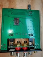
I don't know, but somehow it seems for me that the Layout is probably not the best.
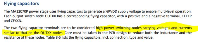
If I see it correctly, the "flying" capacitors are connected very poorly with some extremely small and relatively long traces to the chip. I marked this in red in the picture below.
However the datasheet says, the current / voltages into or out of the flying capacitors are carrying similar currents as on the output-nodes!
Attachments

Thanks maggusxy for the information.
With the MA12070 PCB, has someone connected with an unbalanced input signal, Is there any noise??
Ps: I created a thread to discuss the MA12040 in a box
The little brother: Infineon MA12040 modifications
With the MA12070 PCB, has someone connected with an unbalanced input signal, Is there any noise??
Ps: I created a thread to discuss the MA12040 in a box
The little brother: Infineon MA12040 modifications
Last edited:
which ma12070 pcb?
This one
PL-AD-160 HIFI Digital Class D Power Amplifier Module 2x80W MA12070 Digital IIS | eBay
Attachments

Last edited:
Thanks maggusxy for the information.
With the MA12070 PCB, has someone connected with an unbalanced input signal, Is there any noise??
Ps: I created a thread to discuss the MA12040 in a box
The little brother: Infineon MA12040 modifications
Read my post on page 21.
In the unbalanced connection, IN0B and IN1B are connected to GND, but in this case, noise is generated when the input is open. If you connect it to any input, the noise will disappear. Also, depending on the type of DAC to be connected, noise may be generated when entering sleep mode.
The generated noise is a large level and feels like white noise.
I try to terminate the input with a resistor of around 10kΩ.
This noise issue does not occur with balanced connections.
Last edited:
Interesting point you made about the capacitors... I wonder why?BTL is always 5 level.
Each half-bridge can do a 3-level PWM. Two half-bridges in differential-operation (BTL) is then in fact a 5-level PWM.
So single-ended configuration would be 3-level then.
However the output-filter is interesting. No ferite-bead but instead 22uh filter-inductors without any further LC-capacitors.
Oon
Read my post on page 21.
In the unbalanced connection, IN0B and IN1B are connected to GND, but in this case, noise is generated when the input is open. If you connect it to any input, the noise will disappear. Also, depending on the type of DAC to be connected, noise may be generated when entering sleep mode.
The generated noise is a large level and feels like white noise.
I try to terminate the input with a resistor of around 10kΩ.
This noise issue does not occur with balanced connections.
Hi Toku,
Yes I had read that there was a problem, but I was wondering if anyone had found a way to remove this noise when no signal.
I could be balanced from my DAC, I already have the subwoofer which is connected to XLR, by adding an XLR splitter I can connect the MA12070 in balanced, but I have a 2nd amplifier in the bass and no balanced.
Also there is no sleep mode on my DAC, so the easiest way would be unbalanced and easier to adjust the gains between the 2 amplifiers. The subwoofer as no problem, it is adjusted to -26db.
For now I have started my listening tests with bi-amplification and the MA12040 in the box and the sound is to my taste.
I should order the MA12070, I have a Meanwell 24vdc 200w SMPS so that would be fine.
Denis
Hi,
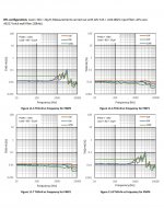
if we look at the distortion measurements in the PDF (40 like the 70), we can see that the distortion rates are higher in the high frequencies on the PMP0 and PMP4 amps, not the case for PMP1 and PMP2.
If it's plugged into BTL, is there a fusion of the first 2 and the last 2, when is the final distortion?
Also another question, can we choose 4 channel mode, and connect only the PMP1 and PMP2? I know that a class D amp becomes unstable if no load is connected, I could always put resistors of good capacity.
Denis
Attachments
- Home
- Amplifiers
- Class D
- Infineon MA12070 Class D