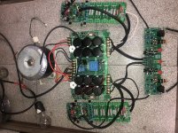
The chassis is build up around a square pipe steel frame, I had it from a old project, the heatsinks I also had, they were 300mm so i cut them in half for better chassis fitting and better airflow, they are pre drilled for to-3, so perfect, they are used and showed a bit wear, so I put them in a mild acid bath, and etched the surface, I looked for anodization company but prices were sky high.
All aluminium is bought on Ebay, a german company the price was very fair, but their metal cutter needs sharpening, the 8mm front plate had been compressed in the cut line, so I had to use a band saw and cut off a few mm, I'm going to phase all edges with a wood router with carbide bit.
So it's quite easy but time consuming, I didn't make a lot of drawings but build it from my mind, a bit risky I admit, driver boards will be shielded with a u shape profile, cause the toroid is pretty close to boards, hmm will add a relay volume control to it.
So make up a drawing , a look for a supplier that is willing to cut materials to your specs, and if possible get a friend who has access to metal working tools, blacksmith cnc operator ?
A good amp deserves a nice chassis, especially if you're married and have to obey the waf factor, I'm playing music on a hiraga 30w without chassis and it's not popular with the misses, so another chassis is needed
Thanks Amplitude.....your cabinet is nice and it’s a great effort ,my 1st 4b fixed in a old cabinet but now I motivated and plan to build one for my 2nd one as you have done. I think anodisation and colouring is little easy process with few chemicals,I watched few videos and thinking to do few trials.There may be someone with CAD drawing for cabinet in this thread who can give us it for🙂 cnc cutting.....
Last edited:
Give it a try, I'm sure you will succeed, let me/us know how the anodization goes, I watched all videos, and " how to" but am not sure the result will be satisfying, uneven colouring and so on, I might be wrong.
There may be someone with CAD drawing for cabinet in this thread who can give us it for🙂 cnc cutting.....
If you need to draw a case in cad, maybe I can help with that part..
Nothing special about cad drawings. Anyone can do that.
It's just a matter of getting into it and learning.
It's just a matter of getting into it and learning.
If you need to draw a case in cad, maybe I can help with that part..
Thanks a lot spookydd...pls do it for all of us, drawing suitable for CNC engraving.
Please do a classic one like original Bryson suitable for 4bsst, better full covering case with heat sink inside the cabinet , letters also for milling,
Please do a classic one like original Bryson suitable for 4bsst, better full covering case with heat sink inside the cabinet , letters also for milling,
Well, to do this properly, I'd need all the necessary data.
It requires good data to get the right result. Garbage in -> garbage out.
And you're referring to engraving as well. What do you have in mind there?
The thing is, I've been making prototypes recently and have been doing various sheet metal based case designs, which I've been trying to get made, but couldn't find a suitable manufacturer, because they all want a fortune to do this.
I Hope , Chalky and Amlidude will assist you as well other experts....
Happy new year.
As I see it theres no final definition of a diy chassis, it all depends on your needs, build, my build incorporated some large capacitors that required big chassis, was it needed? No it wasn't, but that's just me.,
So draw up some sketches that fits your requirements, and dont ask for a pre build solution.
hi to all.
I am in debugging process rigth now. Questions:
What do you mean when you said that the input board must be shorted?
When i conect the bulb, it works like a voltage divisor, so voltage drops. Does it affect anything?
I am in debugging process rigth now. Questions:
What do you mean when you said that the input board must be shorted?
When i conect the bulb, it works like a voltage divisor, so voltage drops. Does it affect anything?
Attachments
Last edited:
Hi.
Short the inputs, yes the bulb affects max current draw, you can't adjust bias, but make it low, try to get dc offset close to zero also, if al works out, you can remove the support wheels, aka bulb, and the final has to be on heatsink, check with multimeter that all transistors are isolated from heatsink before powerup, if you have or have access to a vario transformer use that, otherwise some low amperage fuses will take eventual heat
Short the inputs, yes the bulb affects max current draw, you can't adjust bias, but make it low, try to get dc offset close to zero also, if al works out, you can remove the support wheels, aka bulb, and the final has to be on heatsink, check with multimeter that all transistors are isolated from heatsink before powerup, if you have or have access to a vario transformer use that, otherwise some low amperage fuses will take eventual heat
Thanks. Short input is connect ground to signal?
Do I connect ground from both sides from input board?
Do I connect ground from both sides from input board?
In my first post I didn't see your haven't mounted the output devices, so if all voltages check out according to checklist, all the regulator +/÷ 33 volt, that must be next step
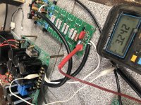
That's the bias voltage you're seeing I think, you can only adjust bias and offset with the output transistors installed, but what you can check is the regulator voltages on input/output board, should be in the neighbourhood of 33 volts
1. Ensure that all components are of acceptable quality and properly installed;
2. Ensure that all solder joints are free of false soldering and short circuits;
3. Do not install the power tube before power-on and the transformer is connected in series. 60‐100W
Incandescent bulbs, especially all SGND and PGND on the board
Use the GND of the large reservoir;
4. Test whether +/‐V2A (ie C26, C30 capacitor voltage) is after power-on.
+/‐33V or so (all between 31-33V is normal);
5, adjust VR1, the measured output OUT is close to 0V (+/- 10mV);
6. Adjust VR2 and measure R38; R39; R40; R41 The voltage across R41 is the minimum value, and the range is about 0.5‐0.58V (if there is an oscilloscope to test the signal channel, there is no problem);
7, properly install the power tube (must connect the incandescent bulbs in series), adjust VR2
Make Q19 current about 5mA; after removing the bulb, adjust VR2 again to make Q19 current 70-80mA (ie, the voltage across R45 is 23-25mV);
8. Re-adjust VR1 to make the output OUT close to 0V (within +/-10mV);
This post posted by Chalky....1. Ensure that all components are of acceptable quality and properly installed;
2. Ensure that all solder joints are free of false soldering and short circuits;
3. Do not install the power tube before power-on and the transformer is connected in series. 60‐100W
Incandescent bulbs, especially all SGND and PGND on the board
Use the GND of the large reservoir;
4. Test whether +/‐V2A (ie C26, C30 capacitor voltage) is after power-on.
+/‐33V or so (all between 31-33V is normal);
5, adjust VR1, the measured output OUT is close to 0V (+/- 10mV);
6. Adjust VR2 and measure R38; R39; R40; R41 The voltage across R41 is the minimum value, and the range is about 0.5‐0.58V (if there is an oscilloscope to test the signal channel, there is no problem);
7, properly install the power tube (must connect the incandescent bulbs in series), adjust VR2
Make Q19 current about 5mA; after removing the bulb, adjust VR2 again to make Q19 current 70-80mA (ie, the voltage across R45 is 23-25mV);
8. Re-adjust VR1 to make the output OUT close to 0V (within +/-10mV);
Turns out that the setup procedure in the debugging instructions is wrong. Bryston recommend that there should be 25mV across a corresponding PAIR of emitter resistors ( i.e. about 12.5mV across a single resistor ) in a fully warmed up amplifier; whereas the debugging instructions suggest 25mV across a SINGLE emitter resistor. So it turns out that your 10mV setting is only a little lower than the Bryston suggested value of 12.5mA.
Attachments
- Home
- Amplifiers
- Solid State
- Bryston 4B SST clone