Is it just a coincidence the Rpi out and andrea clocked fifo closely align at low frequencies?
When you say crosstalk, I assume you don't mean between input and output
When you say crosstalk, I assume you don't mean between input and output
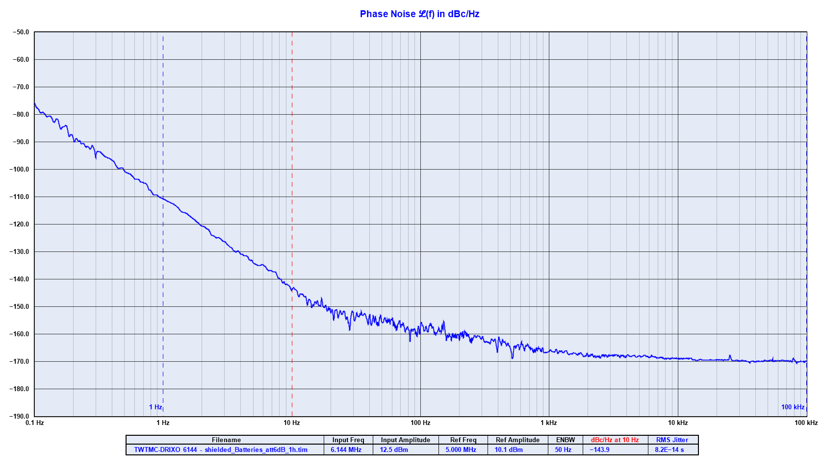
If it is a standard RPI, its close-in pn is remarkable. -115dBc/Hz at 1Hz given that: Raspberry Pi B+ Digital Audio | H i F i D U I N O
Something is fishy here 🙂
It is better than the andrea Driscoll 6.144 MHz at 1 Hz.
//
Something is fishy here 🙂
It is better than the andrea Driscoll 6.144 MHz at 1 Hz.
//
Is it just a coincidence the Rpi out and andrea clocked fifo closely align at low frequencies?
When you say crosstalk, I assume you don't mean between input and output
I think yes, the Driscoll oscillator runs at 22 MHz while the RPI LRCK was measured at 192kHz, there is a huge difference between frequencies.
The RPI LRCK is divided down several times therefore the phase noise decreases.
Below 10 Hz from the carrier the FIFO with Crystek oscillator has worse phase noise, maybe because of the higher phase noise of Crystek.
It's difficult to say because it looks like the phase noise is dominated by the noise floor of the FIFO.
The crosstalk is between LRCK and BCK, I don't know where it comes from because I don't know the design.
I would assume it comes from the reclocker of the FIFO but it's only an hypothesis.
If it is a standard RPI, its close-in pn is remarkable. -115dBc/Hz at 1Hz given that: Raspberry Pi B+ Digital Audio | H i F i D U I N O
Something is fishy here 🙂
It is better than the andrea Driscoll 6.144 MHz at 1 Hz.
//
Where have you seen -115dBc at 1 Hz from the carrier?
This is the RPI LRCK not the master clock, it's divided down several times therefore the phase noise improve (theoretically by 6dB each division).
You cannot compare 6 MHz with 192kHz divided down several times.
You cannot compare 6 MHz with 192kHz divided down several times.
It depends on the DAC architecture, for example it's true for the TDA1541A and the AD1862 but not for the PCM1704 and PCM1794.
Neither for all Sabre DAC.
However since the master clock is divided down almost 100 times the phase noise should be better.
Neither for all Sabre DAC.
However since the master clock is divided down almost 100 times the phase noise should be better.
OK. When you power up the 1021, are you planning to do pn measurements where it counts i.e. on the corresponding LRCK?
//
//
Yes, I will measure the LRCK phase noise that's the critical clock for the DAM1021.
Maybe I will also measure the master clock from the SI514.
It looks like it runs at 45/49 MHz therefore the Timepod does not reach these frequencies (up to 30 MHz) but I'm building an down converter board to get the Timepod measuring up to 100 MHz.
Maybe I will also measure the master clock from the SI514.
It looks like it runs at 45/49 MHz therefore the Timepod does not reach these frequencies (up to 30 MHz) but I'm building an down converter board to get the Timepod measuring up to 100 MHz.
At what frequency is the R2R ladder of the DAM1021 clocked? Sampling frequency or higher?
From your explanation one might infer that if you divide down low enough the phase noise hardly matters. Which is not possible for a massively oversampled S-D DAC, but fine with many R2R DACs...
From your explanation one might infer that if you divide down low enough the phase noise hardly matters. Which is not possible for a massively oversampled S-D DAC, but fine with many R2R DACs...
I don't know, but I believe from 44.1 kHz to 3.072 MHz depending on the oversampling.
I don't know if the DAM1021 applies always the oversampling or it depends on the filters.
With the tweaking the max sample rate will be 384 MHz with oscillators at 22/24 MHz (double of the needed frequencies because it will run with stopped clock).
It's true that dividing down the master clock the phase noise improves but there are other variables to keep in the right consideration:
- the quality of the master clock
- the quality of the dividers
- the circuit between the dividers and the DAC
Let assume 44.1 kHz sample rate, I2S full 32 bit (the worst case), so 44100 x 64 = 2822400 bit per second.
Using 8Mb SRAM you get around 2.9 seconds stored in the buffer: 8192000 / 2822400 = 2.902494....
Assuming 100ppm of frequency deviation you loose around 283 bit per second: 2822400 x 100 / 1000000 = 282.24
So the buffer will be full or empty after around 8 hours: 8192000 / 283 = 28946.996 seconds, or 482.45 minutes or 8.040832 hours.
Then around 4 hours with the latency set to 4 Mb, 2 hours to 2 Mb and 1 hour to 1 Mb (assuming no buffer balancing along 8, 4, 2 or 1 hour).
Hmm, just to get it out of my head.... so my calc's as experiences using 30 year's ago using a single sample SPDIF receiver who provided under / over run detection's.
Here it goes with my math

1. I deal with pure PCM samples, while for easier understanding
2. The used marketing bit's on HW as up to 32 do not count
3. An over / under run happens if one sample gets completely lost (overrun) or has to be repeated (under run)
4. So for a 44.1kHz SR we get a sample time of 1/44'100Hz = 22.675 uS
5. The time as on [3] will happen is dependent of the sample time difference as on the used clocks
6. this means, the differences will be dependent of the two used clocks (crystal osc) as given in ppm (parts pro million)
7. A change over time, while the clocks have to head up, I have seen in addition, a difference of 10ppm after one hour. Could be even more. All dependent of the given HW
8. So after one hour, we may see a +/- of 50ppm of the clocks as on the SR.
9. Now the calc... the time when a sample is overrun / under run is dependent of the difference of the clock freq. as ppm.
10. as X = 10ppm = 10E-6 and as 1 / X = 100'000
11. this means for 1/ X, it is the factor how may samples have to pass until we get the ugly overrun /under run.
12. as from [10 & 11] 1 / X = 100'000 samples have to pass
13. so [4 & 12] the overrun / under run time will be for 44'100Hz as
100'000 x 22.675 us = 2.2675 seconds (units in seconds verified too)
14. now you have a single bit x 8M RAM, latency for 4M,
this means 8192'000 / 2 / 32 bits / 2 channels = 64'000 stereo samples = 1.4512 seconds
15. compare now [13 & 15], it would be hardly to fulfill 10ppm clock speed differences
16. in other words you need a XVCO with smart regulation
17. 30 ago, I did it using a DAC'VCO & PIC control, so no PLL was involved, as both freq. went freely without any phase lock, only smart freq. regulation as at that time using only one sample FIFO. 😀
so you may review the calc's 🙂
Many I understand why the R-2-R ladder was born, no any more PCM1704 in production, but keep in mind the usided FIR oversampling will IMHO still loose against the 2.x MHz spilne oversampling as used in the Wadia 27, later on the provided the uplink to the CD player so the Master clock was at the DAC (Jocko Homo thesis completed).
Also as you told about the cap's FPGA to shift registers, this would be NEVER EVER implemented in a professional gear. IMHO not worth to revamp the DAC while homeworker art at works.
my 2 cents about
Hp
I believe you are getting confused with the FIFO safety against over running and under running, I have already exposed the math in post
Implementing a true FIFO buffer with low phase noise clock on the Soekris DAM1021 DAC
What was not clear?
And moreover this is the worst case because the FIFO is balanced every time there is no music.
So no risk.
And sorry but I have not understood what do you mean wit "Also as you told about the cap's FPGA to shift registers, this would be NEVER EVER implemented in a professional gear."
I believe you are getting confused with the FIFO safety against over running and under running, I have already exposed the math in post
Implementing a true FIFO buffer with low phase noise clock on the Soekris DAM1021 DAC
What was not clear?
And moreover this is the worst case because the FIFO is balanced every time there is no music.
So no risk.
And sorry but I have not understood what do you mean wit "Also as you told about the cap's FPGA to shift registers, this would be NEVER EVER implemented in a professional gear."
Your findings about the implementation:
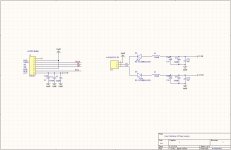
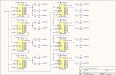
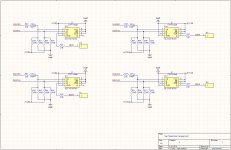
>>Indeed every signal coming from the FPGA is decoupled using a capacitor.
LRCK and DATA have also a pair of resistors on the 595 input pins. These resistors set the the input pins of the LVC595 to half VCC, around -2V (one resistor is tied to -4V and the other to ground) for the upper banks and +2V (one resistor is tied to +4V and the other to ground) for the lower banks.<<
>> What was not clear?
did you ever started to implement (providing over / under run states) and measured/detected those states? Also easy to listen using a 10kHz sine 😀
Hp
Well, it's not my design.
However the listening will tell if it did worth.
I believe it will worth because anyway it will run with better timing using real low noise fixed oscillators.
We are still testing the FIFO, I will let you know soon.
Although I'm sure there will be any of the issues you have pointed out because "the math is not an opinion".
Finally the FIFO balancing will work similar to Ian's FIFO and Allo Kali and no users have reported such that issue using these devices.

No, the input of the interface board is custom protocol PCM.
The input of the FIFO Lite is I2S.
The input of the FIFO Lite is I2S.
- Home
- Source & Line
- Digital Line Level
- Implementing a true FIFO buffer with low phase noise clock on the Soekris DAM1021 DAC