Anyone elses Horn Resp glitching? if I don't touch certain variables in the editor it won't activate the save button.
if I don't touch certain variables in the editor it won't activate the save button.
By "editor", do you mean the Data File Editor, or something else, perhaps? If you are referring to the Data File Editor then the Save button should always be enabled. I am not sure what you mean by "certain variables" - some additional information on the problem, together with a specific example if possible, would be most helpful.
Attachments
Two things I notice....on BR the impulse does not sim correctly (I think?) its neglecting the port?...
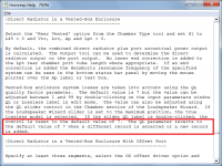
When in offset horn loudspeaker wizard (this is the "editor" I meant)...I can adjust l12 par and l23 par and the save button won't activate...I think its just unique to offset driver wizard though...
When in offset horn loudspeaker wizard (this is the "editor" I meant)...I can adjust l12 par and l23 par and the save button won't activate...I think its just unique to offset driver wizard though...
Hi camplo,
As far as I know, the Hornresp bass reflex impulse response results should be correct. They have been checked against those produced by simulation software developed by Dr. Bjørn Kolbrek (for his own use).
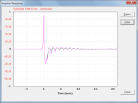
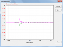
Hornresp definitely takes the port into account. This can be seen in the attached screenprint, which shows the impulse response for the Input Wizard-generated normal bass reflex system in green, and the response for the same system but with Ap changed from 50 to 100 sq cm, in pink.
Thanks for this feedback, you have identified a bug that will be fixed in the next update. It appears that the Save button is enabled when the slider control is moved, but not when the arrow at either end of the bar is clicked.
Kind regards,
David
on BR the impulse does not sim correctly (I think?) its neglecting the port?
As far as I know, the Hornresp bass reflex impulse response results should be correct. They have been checked against those produced by simulation software developed by Dr. Bjørn Kolbrek (for his own use).
Hornresp definitely takes the port into account. This can be seen in the attached screenprint, which shows the impulse response for the Input Wizard-generated normal bass reflex system in green, and the response for the same system but with Ap changed from 50 to 100 sq cm, in pink.
When in offset horn loudspeaker wizard I can adjust l12 par and l23 par and the save button won't activate...I think its just unique to offset driver wizard though...
Thanks for this feedback, you have identified a bug that will be fixed in the next update. It appears that the Save button is enabled when the slider control is moved, but not when the arrow at either end of the bar is clicked.
Kind regards,
David
Attachments
Last edited:
Hi
Here is an example of what I am seeing? one is the BR and one is a BLH...maybe I am excecting the wrong thing...both are created with the same port dimensions and box volume...

Here is the port vs combined...

(edit; I just noticed some more glitches so maybe its just local to my machine? I changed QL spec and then if I save and leave wizard, and click "Next" it doesn't ask to save?)
Can you help me with something else as well? I was wondering how to interpret the Tal spec? For example I have the setting at 5.9....So am I expected to start around 5.9cm of insulation on my cabinet walls?
Thank you.
Here is an example of what I am seeing? one is the BR and one is a BLH...maybe I am excecting the wrong thing...both are created with the same port dimensions and box volume...
Here is the port vs combined...
(edit; I just noticed some more glitches so maybe its just local to my machine? I changed QL spec and then if I save and leave wizard, and click "Next" it doesn't ask to save?)
Can you help me with something else as well? I was wondering how to interpret the Tal spec? For example I have the setting at 5.9....So am I expected to start around 5.9cm of insulation on my cabinet walls?
Thank you.
Attachments
Last edited:
Here is an example of what I am seeing? one is the BR and one is a BLH...
Could you please post screenprints of the Input Parameters windows for your two example designs.
I changed QL spec and then if I save and leave wizard, and click "Next" it doesn't ask to save?
See the highlighted section in the attachment.
So am I expected to start around 5.9cm of insulation on my cabinet walls?
Assuming that the Fr resistivity value you are using is correct, then yes.
Attachments
Thanks for the clarification on the damping. I noticed my IR window for the BR says masked but I'm not sure why.
Youre looking, youre using horn response as a learning tool, not just a ‘speaker’ building tool! this is and will always be the way it shall pave the yellow brick road. We all can find our way if we want to learn. Its ironic they made a movie to foreshadow the inevitable. put your ruby red slippers on and David Mcbean will be waiting in OZ with the answer. not the wizard behind the curtain, but the wisdom it represents that was found! I cant stop finding ways to use Horn response! It has boundaries, but those arent limits.
Last edited:
I noticed my IR window for the BR says masked but I'm not sure why.
Hi camplo,
To compare "like with like", the following changes need to be made:
1. Adjust the dimensions specified for the two systems as necessary, to make them identical.
2. Add a 5.99 cm end correction to the BLH port tube. This is included automatically when the BR design results are calculated.
3. Set the path length in the BLH design to 45.0 cm to make it the same as that specified for the BR design.
4. Select the Tools > Options menu command and set the chamber resonances to 'Not masked'. Otherwise resonances will be masked in the rear chamber used as the enclosure in the BR design, but will not be masked in the BLH design.
5. Set QL to Lossless when calculating the BR results.
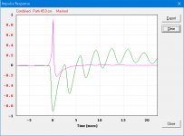
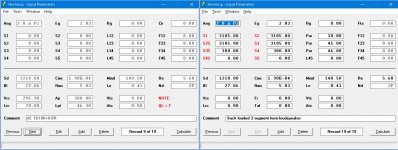
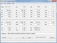
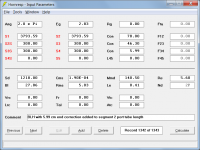
Using the BR record as the reference, the BLH input parameters screen should look as shown in the first attachment (BLH.png)
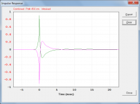
The second attachment (IR.png) compares the impulse response results for the two designs. The BR trace is green and the BLH trace is pink. The two traces are identical but with opposite polarities. This is because of the polarity convention used in Hornresp - when looking at the schematic diagram, the right-hand side of the driver diaphragm is assumed to have positive polarity and the left-hand side negative polarity. When calculating the impulse response, the observation point is assumed to be on the direct radiating side of the diaphragm in all cases. This means that the impulse response for the BR design has positive polarity, and impulse response for the BLH design has negative polarity, exactly as shown in the attachment.
The third attachment (BLH1.png) shows an alternative way of specifying the BLH design, using the throat chamber rather than segment 1 to specify the enclosure. This means that it is possible to compare BR with BLH1 with chamber resonances masked, because both systems have similarly-dimensioned "chambers". The 'resonances masked' impulse responses for BR (with QL = Lossless) and BLH1 are shown in the fourth attachment (IR1.png). Once again the BR trace is green and the BLH1 trace is pink, and the two traces are identical but with opposite polarities.
Hope this helps to clarify things.
Kind regards,
David
Attachments
Youre looking, youre using horn response as a learning tool
Exactly the way I was hoping Hornresp would be used, by inquiring minds... 🙂.
4. Select the Tools > Options menu command and set the chamber resonances to 'Not masked'. Otherwise resonances will be masked in the rear chamber used as the enclosure in the BR design, but will not be masked in the BLH design.
Ty for the guidance.
I guess my first question is why would you want to mask the resonance, and without it, isn't it an inaccurate picture of the system?
Last edited:
why would you want to mask the resonance
Hornresp is one of the few loudspeaker simulation programs that can take chamber resonances into account. A user might wish to mask the resonances when comparing the results against those of other programs, or to mask the resonances when they know that absorbent material will be added to the constructed chamber to dampen the resonances anyway.
without it, isn't it an inaccurate picture of the system?
The option only masks chamber resonances, it does not mask the fundamental resonance of the system. The most accurate picture of the system is with resonances not masked, unless it is intended to add unspecified absorbent material to the final product, as mentioned above.
Hornresp is one of the few loudspeaker simulation programs that can take chamber resonances into account.
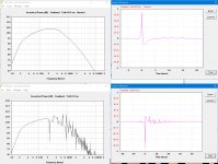
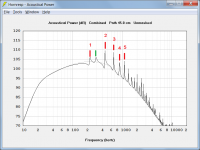
Just to explain further, most programs treat chambers as simple acoustic compliances. Hornresp does this when the 'Masked' option is selected, but uses a more rigorous model when the 'Not masked' option is selected. In the attachment, the grey trace shows the response of the previous BR test example with resonances masked (chamber treated as a simple acoustic compliance) and the black trace shows the response for the same system with resonances not masked (more rigorous model used).
The specified chamber length Lrc is 78 cm, meaning that the half-wavelength frequency is 221 hertz. The resonance peaks indicated by the red lines are due the reflections in the chamber, and are spaced at multiples of the half-wavelength frequency.
The frequencies of the first five resonances, rounded to the nearest whole number, are:
1 221 Hz
2 441 Hz
3 662 Hz
4 882 Hz
5 1103 Hz
The peak indicated by the green line is due to the presence of the port tube. The frequency at which this peak occurs depends on the length of the tube.
Attachments
Last edited:
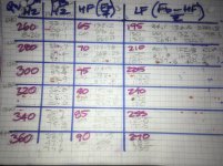
I feel silly, ive been drawing multiple sine waves over Qw pipes and compound qw pipes, Tapped-compound pipes ‘to scale’ and in qw equivalents with Harmonics and then using charts for all the associated frequencies and lengths in qw or half and full to choose how to fold them up in a way to make each segment land on the equivalent of a pressure null that exists as a pipe from a closed end. its Relatively easy in OD, 80cm L12 and two 80 cm following. But in offset driver Closed mouth i can stretch this into another ‘phase aligned result’ which seems to get even better.
All proven and well documented...
Now, in tapped horn(pipe) TH, i have found 120 cm as L12, then 120cm and 80 cm then, but 0.01 as L45 will also phase align. As will zero offset(L12 as 0.01cm) 120cm and 120 split in L23/L34, with L45 as 0.01cm, then placing 80 cm into Vrc/and Ap/Lp where again, phase aligned is found.
Slight adjustments are made to CSA in red segments. No flare or tapered black highlighted inputs for ‘S’.
Beyond this i have found using halfwave or the next tier of fundamental 240cm, or 320cm in compounded, theres the ‘offset’ chunks that are needed to place center to center at a driver, duct, exit per driver diameter or radius (needed to depict the real path and journey, and potential here to be a ‘real’ resukt.
Well, impedance sweeps to log10 or wrapped phase charts help here A LOT!! And the phase angles seen in ‘impedance phase’ helps know what is ‘poosible if assumed as a standing wave, in a folded segment.
Long story short, two out of the last 3 cabinets (complicated multi chamber paraflex and similar have not only dropped on the sim near perfect in ‘timing’, or impedance, wherever you look for ‘clues’, but the response is actually predictably ‘better’ in areas of phase not depicted, because its within the folding as stated, or intentionally shifted and also mirrored as a miniature offset section absorber.
the brain is no good, but the software is making up for that😀 if theres a ‘perfect’ folded qw tuned harmonic compounded and boosted output BW to be found in this manner, its in here, i can see hints of it in every squiggly line that goes straight, or straighter?
there are almost none left to find, i think? either find a single or overlap the two primary peaks in impedance, but consider the folding is easy if you just commit to a few charts of what ‘will’ happen in response, per frequency.
I think, Camplo, we are gonna find a similar idea here soon? i wish we would have realized it long ago when chasing TLs as newbies in the FB groups, and with less ideas or patterns in Frequencies learned by jumping around in the sim🙂 But i think were getting closer?
Attachments
Silly?
I feel silly every time David does a large feature addition to Hornresp. There are things that I still do not really know how to use properly.
But the internal reflection calculation has been there a long time. And I have been taking advantage of it for a long time. I find it amazing how few people actually think about that. I include few in the professional end of this business as well.
Nice to see you figuring it out, and using it to your advantage!
I think???😛
If I force it, by creating a csa change in each ‘segment’. And also apply those at the actual ‘folds’ of the wooden ‘real’ cabinet layout . it seems (?) to trend very very well as compared to summing 3 or 4 seperate parabolic flares (real) as a single of two exp or exp/ parabolic entries. this is unfortunate for the ‘horn impedance match dreamer enthusiast in me, but it is incredible for the potential definition of a segmented pipe expansion thats also ‘victim’ to the reality of ‘folding’? i dont k ie how bad that gets tarnished in the tapped entry i place in there, (like stepped expanded two stage driver @ start and offset to a mid pointroar in series?
But if the use of 320cm compounded ‘horn’ in a 240cm and 80cm split is also folded in the 240 section at 120 and 120 im sitting on a fence of total harmonic phase cohesion with regards to the issues at the point of overlap in the seperate pipes that begin 180 out if phase and at exit have turned a seperate amount in regards to the 240 vs 80 which yields the harmonic of 240cm by the 80cm pipe.
If happy at that qts/Fs and sized for Vas, the driver sits right into amy of these(pic) and (folded once, so divide by 2) at the right hand length is the long pipe, and if you wanna get really twisted in tine vs travel toss it into ‘tapped and try to be accurate with the ‘true’ offset of details like basket radius and the entrance of each side in a fold or csa change.
Shove this type of tomfoolery into a known paraflex, taped horn or type
of type of layout and the whole idea of orbiting the sun with an offset and seasons with a north and south pole rotating and east/west hemispheres suddenly is a result. Or unwrapped phase is a calendar as 360 degrees can be cm or freq can be trimesters and .....
its a bit more than just a speaker now. Im building an actual pipe ‘dream’! no idea when what to do with ‘fake’ perfect Phase. But at least the outputs are aligned from the middle to the ends? the technical details are 60 degrees instead of 90, maybe ?
Attachments
I think I might have come across a minor bug in Hornresp's import routine for BP sims.
1. Go to my sheets site, and download the BOXPLAN-BP6S2 workbook
2. Open the BOXPLAN workbook and on the "Design" sheet, set target S4 to 900 cm^2 and select "Export!"
3. Import the BOXPLAN sim created in step 2, and then select the Bandpass Wizard
4. In the BOXPLAN workbook set target S4 to 1050 cm^2 and select "Export!"
3. In the Hornresp Wizard screen, press F6
Ap1 isn't changed to 1050, as indicated in the sim import file. Instead it's set to 999.9
- Home
- Loudspeakers
- Subwoofers
- Hornresp