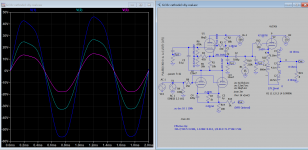
May I ask if anyone has continued to play with this ?
I like the idea to use a DHT at an appropriate current like 20-30mA for a 801A or a 46.
I really like the idea to use a choke to preserve voltage swing and have a reasonable B+...
Are there any more modern approaches ?
I read Alans article on a choke supported mu stage https://www.tiffe.de/roehren/VTV/VTV20.pdf
and as well his outrageous mu stage article with the Kt77 and a much simpler schematic in Audioxpress 5/2019...
I would like to try something like this with my 801A as a driver for 300B...not sure how to do the maths so on these new variants...so, if anyone did already something in that direction, that would be helpful to understand.
Hello, I'm trying to build a mu stage with the 6F12P tube. It's a triode + pentode with a big μ, it seems to me to be a good tube for that but I have all the difficulties in the world to make something that works.
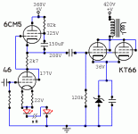
Looking at the 6CM5 curves, it is a far from linear performer. So, how to arrive at a more or less steady current? The 150uF sets the G2 voltage, over the high value 82K resistor. At peaks G2 voltage drops, stabilizing the penthode current. One can always put a potentiometer in its place and follow the empirical route.
What is slightly worrying is the discrepancy between measurement and listening enjoyment mentioned in the above messages 🙂
What is slightly worrying is the discrepancy between measurement and listening enjoyment mentioned in the above messages 🙂
Attachments
6F12p mu stage
You are not alone - quite a few people have worked with this valve with good results. Information and data can be found here: Tube Tester Files - 6F12P and here: 6F12P a great Russian valve – Bartola(R) Valves
I built a prototype 6F12P mu-stage some years ago and my notes tell me that it measured very well - it ran with 12.5mA of current and showed plenty of gain and plenty of drive. I didn't listen to my prototype but couldn't see any reason why it wouldn't sound good. The 6F12P's high gain and high transconductance makes grid-stoppers and good layout a necessity if high frequency oscillation is to be avoided. I used DC heaters and elevated the heater voltage +75V to keep the heater-cathode voltage of the upper pentode stage within the published limit of 100V.
For another approach, M V Toropkin shows a schematic for a 6F12P in a type of mu-stage on page 128 of his 2005 book "Ламповый Hi-Fi УСИЛИТЕл" (which roughly translates as Valve Hi-Fi Amplifiers) which you can find here: https://ideafix.name/wp-content/uploads/stuff/book49.pdf
Hello, I'm trying to build a mu stage with the 6F12P tube. It's a triode + pentode with a big μ, it seems to me to be a good tube for that but I have all the difficulties in the world to make something that works.
You are not alone - quite a few people have worked with this valve with good results. Information and data can be found here: Tube Tester Files - 6F12P and here: 6F12P a great Russian valve – Bartola(R) Valves
I built a prototype 6F12P mu-stage some years ago and my notes tell me that it measured very well - it ran with 12.5mA of current and showed plenty of gain and plenty of drive. I didn't listen to my prototype but couldn't see any reason why it wouldn't sound good. The 6F12P's high gain and high transconductance makes grid-stoppers and good layout a necessity if high frequency oscillation is to be avoided. I used DC heaters and elevated the heater voltage +75V to keep the heater-cathode voltage of the upper pentode stage within the published limit of 100V.
For another approach, M V Toropkin shows a schematic for a 6F12P in a type of mu-stage on page 128 of his 2005 book "Ламповый Hi-Fi УСИЛИТЕл" (which roughly translates as Valve Hi-Fi Amplifiers) which you can find here: https://ideafix.name/wp-content/uploads/stuff/book49.pdf
This is how I do it: First bread board the bottom tube(on the right) by adjusting cathode resistor so the plate is half the HT and desired current. Construct the upper tube circuit by adjusting screen resistor until half HT for each tube.
Attachments
Thanks Koonw.
But i want to use the Alan Kimel schematic.
I wired like this :
150v are wanted.I think that i understood nothing.
How to calculate RP?
[url=https://goopics.net/i/LbQ0p]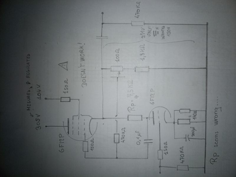 [/URL]
But i want to use the Alan Kimel schematic.
I wired like this :
150v are wanted.I think that i understood nothing.
How to calculate RP?
[url=https://goopics.net/i/LbQ0p]
 [/URL]
Last edited:
How did this circuit perform?
If I understand your circuit Koonw, the 6F12P mu-stage drives the output triode which appears to be a cathode follower - cool!! 🙂 How did it go?
I noticed that the DC voltage at the cathode of the 6F12P pentode is >200V which is well above the published limit Do I have that right? Did you raise the heater supply voltage?
If I understand your circuit Koonw, the 6F12P mu-stage drives the output triode which appears to be a cathode follower - cool!! 🙂 How did it go?
I noticed that the DC voltage at the cathode of the 6F12P pentode is >200V which is well above the published limit
 Do I have that right? Did you raise the heater supply voltage?
Alan Kimmel's circuit
Yes that's what I used too. I had max B+=300V, so I put only 116V across the triode, about 155V across the pentode, so that the last 30V was across the anode resistor of the triode.
I biased both the pentode and the triode at -1V. That gave me 3mA through the triode and I guessed about 15mA through the pentode (the 6F12P dat sheets don't show screen current 😕)
30V and 3mA gives 10kOhm on the triode.
I have attached a cleaned up sketch of my test circuit (the original is very messy because I changed values a lot before I arrived at the final circuit). I was testing many pentode/triodes at the time. The 6F12P worked well, so did the 6KT8, and the 6KR8. My favourite was the 6AH9 compactron (mu=20).
I didn't use a second regulated supply for the screen of the 6F12P pentode (interesting idea) but just tapped it frpom the B+ as Alan suggested.
Attachments
@Bondini , thanks that very kind from you.
I will understand something at the Schematic.
Regulated screen's voltage is an easy way:
You are shure of the voltage value,
No need to calculate a resistor,
A zener diode can be use for several grids.
Noise can be supressed with a capacitor.
I will understand something at the Schematic.
Regulated screen's voltage is an easy way:
You are shure of the voltage value,
No need to calculate a resistor,
A zener diode can be use for several grids.
Noise can be supressed with a capacitor.
6f12p max heater voltage is +-100V, you can raise +100V in this case, cathode potential still exceed the max by 150V for 250V (500/2) HT. I use 6p14p or EL84 and twin sections 12ax7 in real circuit, I think I have leave it floating 🙂
Last edited:
In fact this circuit is difficult to understand because it looks like a control loop. Perhaps it is possible to bias the control grid of the pentode directly to ground with a divider bridge?
 [/url][/IMG]

Last edited:
This is sch of my real amp, not different from Alan Kimmel's circuit. But If the upper tube is 6f12p Pentode you don't want to draw too much current and hence the difference is current division, the bottom tube can carry as much current as upper tube. Btw replacing 4x 6c19p with 1x 6c33cb sounds much better to me, Mu stage driver stage is good to go.
Attachments
Very interesting, Koonw! Could you confirm that your output transformer primary and secondaries are actually in series? If OP allows could you please tell more about this transformer and did you use one or both triodes in the 6C33B?
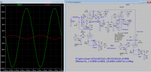
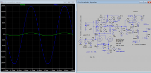
Yes I confirm the OT secondary is connected in series, in correct phase which will induce NFB as shown otherwise it's PFB which resulted in more distortion and I use both triodes of 6c33c. The bottom and top response is much extended in this arrangement than without, still good power output. OT is air-gap, rated 30W , the inductance is measured, and calculated about 200-300 ohms Pri DCR 65 ohms, but maybe due to quality of lamination used HF is rolled off but after NFB from output winding it's much improved.
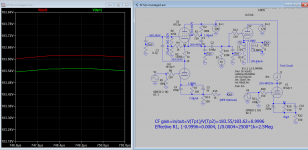
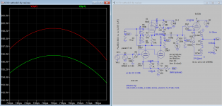
Btw I figure that Effective Rp is 714k<1Meg:
196.7/199.5=0.986, 1-0.986=0.014, 1/0.014=71.4*10k=714k
Btw I figure that Effective Rp is 714k<1Meg:
196.7/199.5=0.986, 1-0.986=0.014, 1/0.014=71.4*10k=714k
Attachments
Last edited:
This is sch of my real amp, not different from Alan Kimmel's circuit. But If the upper tube is 6f12p Pentode you don't want to draw too much current and hence the difference is current division, the bottom tube can carry as much current as upper tube. Btw replacing 4x 6c19p with 1x 6c33cb sounds much better to me, Mu stage driver stage is good to go.
The above "replacing 4x 6c19p with 1x 6c33cb" I actual meant replacing 1x 6c33cb with 4x 6c19p, sorry about the wording.
Hello,
I tried the mu follower from valve wizard without succes.
The Valve Wizard -Mu Follower
I don't understand the grid pentode voltage : why 27 v?
Curent value is only 0,65ma!
I mesured voltages and checked all the resistors value.
Please help.
Regards
 [/url][/IMG]
I tried the mu follower from valve wizard without succes.
The Valve Wizard -Mu Follower
I don't understand the grid pentode voltage : why 27 v?
Curent value is only 0,65ma!
I mesured voltages and checked all the resistors value.
Please help.
Regards

Last edited:
I spot one reason why it does not work. The screen supply is short circuit the signal of the upper tube. Insert a resistor of about 100k after 150 screen resistor to HT2 should fix it. Btw the total current is 9.8mA, if not you may have to adjust HT2 (screen supply) or the cathode resistors of bottom tube.
- Home
- Amplifiers
- Tubes / Valves
- Mu stage driver
