This tek 212 is still at ebay.
As it is have the possibility to run with batteries it's perfect for hunting hum.
Oscilloscope tectronix 212. 2 Channel 2 Channel. near MINT! Shipping World Wide!!! | eBay
As it is have the possibility to run with batteries it's perfect for hunting hum.
Oscilloscope tectronix 212. 2 Channel 2 Channel. near MINT! Shipping World Wide!!! | eBay
You would need to study the circuit regarding the cap. To remove it from the circuit I posted would not be advisable because the regulator is fed via that 10 ohm and that means the impedance at the input to the reg would be very high... not good.
I could understand the cap being removed if the 10 ohm was also shorted out and perhaps also a larger value then fitted for C12.
From what you say about the 'dangly cap' it sounds like the unit has a bit of previous history and so could it possible anything else has been altered or changed?
That could be a valid mod if issues were found with ripple occurring because of the regulator dropping out of regulation under slightly low mains voltage conditions.
So the Mk1 and II circuit has got C35 0.33 uF across the regulator, and mine Rev. E does not, as designed by ARC.
Also Mk1 and II have 2 x 1500 uF smoothing caps, mine has 2 x 1000 uF (C12 and C35....annoyingly this is now also called C35 )
Do you think it is worth adding the .33 uF, could that help?
I also have another 1000 uF cap, could this be added in parallel to the 1st 100 uF or 2nd 1000 uF cap to any good effect (making it like the original Mk1 with 2x1500 = 3000, just now with 3 x 1000 = 3000)
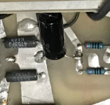
The dangly cap was C16 and my repair guy who put in the wrong FETs...picture attached, I have swapped this for an axial.
Attachments
This tek 212 is still at ebay.
As it is have the possibility to run with batteries it's perfect for hunting hum.
Oscilloscope tectronix 212. 2 Channel 2 Channel. near MINT! Shipping World Wide!!! | eBay
That looks very good. But a scope like any other tool is only as good as its user, same as a hammer, slide rule or vacuum gauge.🙂
Add yours in this space!
If I remember correctly, that model of Tek Scope used NiCad Batteries.
NiCad battery life is limited.
Good luck finding replacement NiCad batteries.
And the description says: Marke: Hameg Wrong. Serial Number is: Built in Beaverton Oregon. Hameg is not in the US.
And, that flat-front CRT with Internal Graticule was made at Tektronix in the original CRT building in Beaverton, Oregon.
It is an Analog scope, nothing digital about it.
Anybody with better history information on that scope?
Last edited:
Have you confirmed no change in hum after tube-rolling? That is one fault-finding action.
Another action is to temporarily disconnect the heater windings to V3/V6, and to V1/2, and then V4/5, and to power them from a battery (noting that V3/V6 is at a hazardous voltage as V3 and V6 are elevated to 133V as they are cathode followers, and have a fixed humdinger) and note any change in hum level.
Another action is to temporarily disconnect the heater windings to V3/V6, and to V1/2, and then V4/5, and to power them from a battery (noting that V3/V6 is at a hazardous voltage as V3 and V6 are elevated to 133V as they are cathode followers, and have a fixed humdinger) and note any change in hum level.
Do you think it is worth adding the .33 uF, could that help?
I also have another 1000 uF cap, could this be added in parallel to the 1st 100 uF or 2nd 1000 uF cap to any good effect (making it like the original Mk1 with 2x1500 = 3000, just now with 3 x 1000 = 3000)
All 78 and 79 type regs should have decoupling close to the regulator pins (between ground pin and Vin) and this is mentioned in all the data sheets as a requirement for stability. In fact for the LM7824 it is listed as 0.33uF.
I wouldn't go randomly changing the design by adding or changing values at this stage because you really need to diagnose where this hum is originating.
There is no harm tagging an extra cap across the existing one as a quick test to see if anything changes but I would not make the swap permanent just on the basis that a larger value seems a better idea... often it is not.
ok - will give it a quick try with an extra 1000 uF, would you tag it on the first one or second one?
actually I have a 500 uF which would work as a test, and be a little less stress on the system I guess.
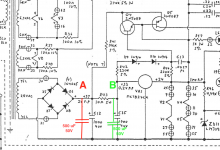
So shall I put it in place A or B do you think to try it? The red pill or the green pill 🙂
Thanks for ALL the excellent advise.
So shall I put it in place A or B do you think to try it? The red pill or the green pill 🙂
Thanks for ALL the excellent advise.
Attachments
ok - will do, BUT just thought about this from earlier 50 Hz measured with a cheap app (maybe app is pants?)
"The power supply with its full wave rectifiers would produce 100Hz rather than 50Hz if for example the noise was caused by ripple on the rails."
But will attempt it any way to have a super quick look
"The power supply with its full wave rectifiers would produce 100Hz rather than 50Hz if for example the noise was caused by ripple on the rails."
But will attempt it any way to have a super quick look
Well that's true if the hum you hear is a pure deep tone with no harmonics but all this is difficult to evaluate at a distance 🙂 without actually having it in front of you and all that...
It only takes seconds to tag them across so just try it.
If you are still getting nowhere then you are going to have to do some serious elimination to try and get a handle on what is happening.
Quickly disconnecting the heaters to those last stages was I think mentioned above (I see... a battery...) but you could just try quickly breaking the circuit and seeing if the hum is suddenly cut of not.
Essentially you end up with just that line stage in circuit and the connections to the volume/balance cut and the input to the stage shorted at the proper ground point. You would also chop other grounds that could possible form a loop but all that needs the unit in front of you to figure out the wiring.
I was curious what the actual official spec was for 'hum' as it seems conspicuous by its absence from the specifications. Only 'wideband' noise is mentioned but with no definition of the limits.
250uV is 0.25mV (quoted in the specs) and that applied to a conventional power amp of say a gain of 20 would generate 5mV of this noise which could be quite audible I would think, particularly with sensitive speakers. If a large part of that noise is a hum residual...
So maybe we are reaching a point where a scope check is needed to try and see what is happening.
So I tried it, unfortunately it does not make a noticeable difference 🙁
I wonder if I can just noodle on making the isolation better in any other new ways? this is what has got me from unacceptable to nearly acceptable....
Yeah the gain is huge, and this makes the pre amp super sensitive in the context of the system. My 211 power amp is of conventional sensitivity driving 99dB/W speakers and the pre amp has 26 dB of gain....
I know there is an option to increase the NF in the pre-amp circuit and whilst I have not actually tired this as I can't imagine this does not come with a SQ compromise? I tried an attenuator in line from pre->power and it cut the sensitivity and noise floor....but also all of the musical dynamics, it just sounded awful.
The only niggling thing I feel indicates that there is still a win to be had is the ridiculously sensitivity of V4 to any touch or proximity of my hand nearby it.
... the ridiculously sensitivity of V4 to any touch or proximity of my hand nearby it.
That sounds a lot like the preamp I'm currently fighting; I think I have an internal ground loop prob. The difference is, I'm building mine, whereas yours is a commercial product from a reputable manufacturer: I've had ARC SP8 & SP10 before, and I can assure you they don't do hum out of the box. The prob should not be a design prob; so yet another hypothesis is the techs you've employed may have created ground loops unknowingly.
At this point, maybe a clear and concise history could help everybody, such as:
- Bought new or used?
- Did it hum when first put into your system?
- If not, how long until the prob shows up?
- What did the 1st tech do? You mentioned a transformer replacement (a rip-off, surely); anything else you can recall?
- What did the 2nd tech do?
- Did you do a visual exam of the internals to determine what has recently been done (shiny new solder) and what is original?
At this point, maybe a clear and concise history could help everybody, such as:
Bought new or used?
HEY I can't believe how much help I am getting on this forum - THANKS!
I bought it used, it had a mechanical hum on the old original transformer, which was sufficiently loud to kind of obscure any speaker hum; so exactly how much hum it had through the channel difficult to guess.
Did it hum when first put into your system?
What did the 1st tech do? You mentioned a transformer replacement (a rip-off, surely); anything else you can recall?
What did the 2nd tech do?
see below, I had the transformer wound to ARC spec as new one from ARC was silly money. All voltages pretty much spot on, and it's mechanically silent
The amp came back from the following work from first guy
Repair details;
R7 300k resistor open cct RIAA stage anode resistor
2N5462 FETS replaced x 4 (wrong ones put in...that failed and gave me huge hiss on line stage)
Mute cct cap & resistor replaced
C16 capacitor replaced v3/6 heater smoothing capacitor (untidy job, I hve put in an axial now)
ZD17 replaced power supply
R87 Replaced ,v8 anode resistor
ECC88 / 6DJ8 X 2 replaced
Transformer mounting plate modified, transformer fitted
Transformer phasing check with scope
If not, how long until the prob shows up?
on return it hummed like crazy, repair guy had it back......and it still hummed like crazy
I had already paid him, took it to another repair guy to fix the hum, he moved/dressed the DC heater cable a bit and replaced a valve...it was a bit better but not sorted.
Did you do a visual exam of the internals to determine what has recently been done (shiny new solder) and what is original?
The work done by the fist tech was as he listed, but obviously he was just swapping parts to see how it improved I guess..
I have since with help from this forum done the following
added some steel partition plates to reduce the hum induced somehow from the mains transformer
added shielding braid to the DC and AC cables near signal/valves
put new FETs in to specification to manage Hiss and get the voltages correct
swapped out C16 in the hope the repair guy did this incorrectly
put new PS (LT and HT) caps in (lots better in sound quality once run in)
added a new volume pot as the old ALPS was a bit scratchy
I have also tried various interrogations,
not earthing in the plug Pre and power (no benefit)
shorting each input (no benefit)
swapping valves (no benefit)
valve cans earthed or not (no benefit)
voltages on circuit are all nearby to specification
Oh I also bypassed the optocouplers as the auto mute used to hum rather then mute and I hoped they were to blame. Probably helped a bit, but did improve SQ with them out of the way.
How about as a test removing the transformer completely and wiring it via leads to give some serious physical separation and see if that does anything.
An awful lot has been done and by the sounds of it not so well 🙁
An awful lot has been done and by the sounds of it not so well 🙁
How about as a test removing the transformer completely and wiring it via leads to give some serious physical separation and see if that does anything.
An awful lot has been done and by the sounds of it not so well 🙁
I had thought of this, but for me this is quite a lot of work.
As a solution can you run AC through an umbilical? keeping the transformer in a separate box/case. How could this work practically?
...
I bought it used, it had a mechanical hum on the old original transformer, which was sufficiently loud to kind of obscure any speaker hum...
Mea culpa.
This is actually the exception to what I said before (... ARC... don't do hum...). I had a D90 (power amp) that had a mechanical hum/buzz that's light to moderate, audible from a foot or so. That was common to lots of ARC's from the 80's.
A digital scope is complicated and I find it hard to dial in, get clarity, etc, and too many damn menus. I like old Leader scopes that were popular in trade schools. Built in Japan at a time when Japan seemed to be making everything to mil quality, and they didn't use many proprietary ICs like many other brands. And always available on ebay. Dual trace would be handy to display the input and compare that to downstream points.
I had thought of this, but for me this is quite a lot of work.
As a solution can you run AC through an umbilical? keeping the transformer in a separate box/case. How could this work practically?
I was thinking of doing this more of a way to eliminate the transformer as a possible suspect, the outcome of which would determine what to do next.
It doesn't have to look nice 🙂 just be physically removed as a test. If it makes no difference then it all goes back as it was.
If you think of doing this then mark and write down where every wire goes and also take pictures for reference.
- Home
- Amplifiers
- Tubes / Valves
- cheap oscilloscope? to help find my damn hummmmm