If you start with 25V unloaded I think 21.4V is quite low when loaded (1.5A bias) as your transformer looks quite large.
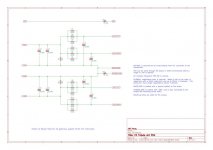
I think it will be easier if I include a crc diagram. I have exactly the same but without AC line. When I'll be home I warm up the amp and give you the exact values before the bridge and before crc.OK, so -+21.4 VDC are the rails as (D)rains of mosfet's are connected to rails. But if you go from 2 x 18 VAC which is about 25 VDC when rectified to DC....it is a large voltage drop from 25 V to 21.4 V. I remember that you have measured higher rails?
What is your total R in the CRC filter's? ....you have 7 parallel resistors?

Without load, I have 18.3VAC before the bridges and 23.6 / 23.7 VDC before the CRC. Loaded power supply today showed 18VAC and +/- 21.7VDC on all rails.
The Drains on the mosfet's should be the same as the rails?
Is it variation on mains that you now have 21.7 and not 21.4?
I think you end up with quite low rails. I would expect something like 22.5 VDC loaded.
But it is probably due to maybe not very many uF in PSU so ripple is quite high so you end up with a bit lower rails than most others.
Is it variation on mains that you now have 21.7 and not 21.4?
I think you end up with quite low rails. I would expect something like 22.5 VDC loaded.
But it is probably due to maybe not very many uF in PSU so ripple is quite high so you end up with a bit lower rails than most others.
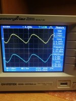
I don't know why there is this 0.3V voltage fluctuation. Maybe a mains , maybe my cheap DMM? The ripple is at 170mV, but it was checked with my inaccurate oscilloscope. I have a total of 178,000 uF on the power supply. Do you think it's not enough?
I see that the loss on the bridge is about 2v and the same drop is when connecting the amplifier boards. Is it too much?
I know ... Lots of questions from noob 🙂 I try to understand what I'm doing, if there are any mistakes I am doing.
I see that the loss on the bridge is about 2v and the same drop is when connecting the amplifier boards. Is it too much?
I know ... Lots of questions from noob 🙂 I try to understand what I'm doing, if there are any mistakes I am doing.
2V voltage drop is probably about right for the bridge.
18VAC x 1.4 = 25.2 - 2V (bridge) - 0.16V (R in CRC) = 23 V.
I just wonder where the remaining 1.3 V voltage drop is hidden.
I think it is normal to use 22.000 uF caps for these PSUs. I have not made a ripple calculation but 170 mV seems high. I have less after my CRC (Universal PSU from DiyStore) but I use 33.000 uF caps and have mono blocks and I have 11 mV RMS on each rail after CRC (just measured). Then after CRCLC I have "nothing".....almost.
If you're going to engineer an input stage daughter card, you'll need a test fixture. One of the ones I used is shown below. It includes BNC connectors for extremely low inductance ground connections, much lower than a scope probe's ground wire + crocodile clip. This is needed when doing 2 nanosecond risetime square wave testing; any parasitic inductance in the ground leads will ruin the waveshape very quickly! Of course SMB or SMA connectors would have been even better but I didn't feel like spending that kind of money.
I included (socketed) inductors in series with the power supplies, to assess the input stage's propensity to oscillate if the power supply PCB traces (on the M2X mother board) are very long. I also included (socketed) load resistors to see whether the input stage's performance degraded whe driving the ~600 ohm input impedance of the Edcor transformer + output stage components. And I included (socketed) load capacitance too, to find out whether the input stage becomes unstable when driving a capacitive load.
Sockets let you quickly change a component value, or remove it entirely, or replace it by a short circuit. As you begin testing your input stage board(s) I think you'll quickly learn which of the socketed parts has the greatest effect, and which are essentially dont-cares.
_
Mark, thanks for this view of the Mountainview DB. It is the only one I found in this forum.
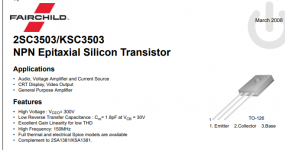
Do I have this right, regarding Q1-Q3, does the emitter lead [#1] go in the first hole with the square on the circuit board?
Thanks
Attachments
It was 170mVpp 56mV RMSView attachment 900256
OK, 56mV RMS......it might be correct as I have 11 mV RMS. You have double current and less uF in Caps.....
It is just strange if you can hear 250 Hz noise and with speakers that are not very sensitive?
I'm in need of one IPS#6 and one IPS#7 daughter board PCB. If anyone has a couple boards I could buy please PM me.
Looking forward to IP#8. One can never have too many daughter boards.
Looking forward to IP#8. One can never have too many daughter boards.
Hey AB Mark always sends and extra board of each in case of mistakes or smoke... You can have my one of each if another member will send you their spare boards. 🙂
yeah, Mark generously sent me 3 each when I built my first set. I'm making a M2X with all the boards for my son for Christmas so I need one more of each board.
I'm just doing what is right... from Nelson on to the peeps that help me. It's rewarding to be able to help one help another. Nuff said, get me an address, and how soon.
JT
JT
I need to work on my grammar. What I meant to say is that @6L6 has already collected my address so he can send me the boards.
@thompsontechs offer still very much appreciated. If anybody needs and extra board, you know who to ask...
@thompsontechs offer still very much appreciated. If anybody needs and extra board, you know who to ask...
Mark, thanks for this view of the Mountainview DB. It is the only one I found in this forum.
Do I have this right, regarding Q1-Q3, does the emitter lead [#1] go in the first hole with the square on the circuit board?
Thanks
Please disregard this post.
Has anybody made a small "test bench" for testing M2X input boards before they are put into work on amp board?
Not so much a test bench, but I did check the original 5 cards individually prior to installation for basic DC voltages. I did not check AC signal performance.
I wonder if a spare M2X amp board can be used and then only build the interface for the input board (screw stuff) and front-end to input board with 100k to ground etc. If PSU connectors is also installed it is easy to power the input board. Then input wires with a RCA connector.
For IPS#6 board it could be nice with at least a resistor to Gnd so there is not a floating JFET gate if powered up as "stand-alone".
For IPS#6 board it could be nice with at least a resistor to Gnd so there is not a floating JFET gate if powered up as "stand-alone".
- Home
- Amplifiers
- Pass Labs
- The diyAudio First Watt M2x

