Don’t mod anything Tony until we have found your noise source!! Clearly this is not coming from the kx-Amp if it’s still there when the amp is powered down.
Changing the input filter on the amp will not help this issue.
My guess (and it’s only that at this stage) is that if the noise is not there when you short the probe tip to the ground clip, then the noise is coupling through the electric field ie capacitively which would make sense given the frequency. Looks like something with very fast rise times is causing this.
Attachments

Last edited:
Here's a quick and dirty model to demonstrate HF noise coupling from a SMPSU like a wall wart. In this example, the burst ringing is at 11 MHz at c. 15us intervals - if the leakage inductance L1 is reduced or the diode capacitance is reduced, the ringing frequency will go up.
Attachments
Last edited:
Don’t mod anything Tony until we have found your noise source!! Clearly this is not coming from the kx-Amp if it’s still there when the amp is powered down.
Changing the input filter on the amp will not help this issue.
My guess (and it’s only that at this stage) is that if the noise is not there when you short the probe tip to the ground clip, then the noise is coupling through the electric field ie capacitively which would make sense given the frequency. Looks like something with very fast rise times is causing this.
Hi Bonsai,
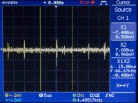
Is the attached Pic what you're looking for?
Time between 3 pulses is 15 uS ergo 7.5 uS between two (as per cursor positions)
Not easy to capture as they peak and fall quite a bit - averaging doesn't work so I had to use 'single shot' a few times to get something half decent.
If it's a 'wall wart' going to be fun to find as we have plenty plugged in all over the house 🙁
Cheers and thanks for all the help.
Attachments
Take out your good-down-to-1-picofarad LCR meter and measure the capacitance between two balls of aluminum foil, each ball 10cm in diameter, spaced 75cm apart. It will give you an appreciation of the appropriate "C" value to use in bonsai's simulations. How far away is the nearest wall wart? The second nearest?
Here's a lower cost good-down-to-1-picofarad meter that I use quite often: link to UK eBay
Here's a lower cost good-down-to-1-picofarad meter that I use quite often: link to UK eBay
Take out your good-down-to-1-picofarad LCR meter and measure the capacitance between two balls of aluminum foil, each ball 10cm in diameter, spaced 75cm apart. It will give you an appreciation of the appropriate "C" value to use in bonsai's simulations. How far away is the nearest wall wart? The second nearest?
Here's a lower cost good-down-to-1-picofarad meter that I use quite often: link to UK eBay
Thanks Mark
I'll give the Al 'balls' a try tomorrow. My Atlas "Peak" LCR meter goes down to 1.0 pF
Plenty of wall warts on the same ring mains in the room (my son has aquariums there with plenty LED lights and other paraphernalia) - but I did switch them off at the wall previously - as I did my PC that has a UPS.
However I switched off the UPS at the wall - not the front panel.
From a web search it seems that 133 KHz is a "standard" for UPS control purposes and I guess the UPS circuits remain powered if there's a mains interruption. 😱
Looks like SMPSU noise. The frequency is in the ball park as well (might be a standard push pull forward converter with CT transformer so you’re getting the pulses 7.5 us apart. The different magnitude of the pulses tho seems to support this conclusion - seems to toe in with the UPS thing also.
@Mark - that’s a very good way of looking at it to gain an appreciation of the issue - two balls of foil. 🙂
@Mark - that’s a very good way of looking at it to gain an appreciation of the issue - two balls of foil. 🙂
Last edited:
Looks like SMPSU noise. The frequency is in the ball park as well (might be a standard push pull forward converter with CT transformer so you’re getting the pulses 7.5 us apart. The different magnitude of the pulses tho seems to support this conclusion - seems to toe in with the UPS thing also.
Well I switched off the UPS both at the wall and on the front panel and nothing happened 🙁
Turned off everything else in the room then tried the other rooms (at the wall sockets), security system (At the wall - which has a fairly large separate voltage adapter connected by a cable to the plug - so not sure if it's transformer or SMPS - but the security has a battery backup), satellite decoder, Internet router (and Fibre line) but without success.
Moved the scope to the dining room (I know the plugs there are on one circuit) and got a different waveform varying form around 2 to 7 MHz.
Bypassed the surge protector bank that the scope is normally plugged into and found no difference in my office/workshop.
Today I'm finding that the main pulses are measuring 10 nS between them rather than 7.5 nS yesterday - but there are now more 'spikes' around at other frequencies than there was yesterday.
So next step will be to switch off circuit by circuit at the main DB when I have chance.
Also, as it's an old house, I need to check the main earth connection as well - perhaps the cable clamp is corroded or similar)
I'll get back to you when I can when I have more details.
Thanks for the help as always.
Interesting problem. Could be this is also line conducted - in other words it’s coupling capacitively onto the mains and then conducted through the wiring. Might even be from the neighbors, or maybe Escom control panel in your street.
There’s a huge amount of HF garbage out there - just a fact of life nowadays unfortunately. You only need one bad SMPSU to cause havoc in a house if you’re trying to do low noise work.
I bought a bunch of ferrite cable clamps and they can help sometimes with CM conducted HF noise - you just clamp them over the mains cables. They won’t help if it’s field coupled though - only screening will help but the best solution always is to fix the problem at source.
These two links are quite helpful. If you think YOU'VE got problems, imagine how much worse it is for people receiving shortwave radio transmissions from 5000 miles away.
K9YC Publications
http://audiosystemsgroup.com/RFI-Ham.pdf
K9YC Publications
http://audiosystemsgroup.com/RFI-Ham.pdf
I have the boards complete again, and added 1k resistors, silver mica compensation caps, tried a 1W carbon film resistor for R25, 'audio' input caps.
I tried measuring distortion with and without R42 (1p vs 2P comp), but cant make out any difference using my (slightly worse) Asus sound card, so I guess that could be a choice based on listening preference.
I made the measurements 'worst case' using low bias, 3,5ohms load, and fairly high output level, to be sure it's going out of class A operation. To my thinking, this would make the compensation in the feedback more critical, since there are more distortions to compensate.
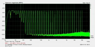
Below is an example of the multitone test.
Feeding it square wave I see no signs of instability with or without the R42 resistor. Only a very small and rounded overshoot without load with the R42 resistor connected. This slight overshoot goes away with load connected. Overshoot is not present without it (1P comp).
I tried measuring distortion with and without R42 (1p vs 2P comp), but cant make out any difference using my (slightly worse) Asus sound card, so I guess that could be a choice based on listening preference.
I made the measurements 'worst case' using low bias, 3,5ohms load, and fairly high output level, to be sure it's going out of class A operation. To my thinking, this would make the compensation in the feedback more critical, since there are more distortions to compensate.
Below is an example of the multitone test.
Feeding it square wave I see no signs of instability with or without the R42 resistor. Only a very small and rounded overshoot without load with the R42 resistor connected. This slight overshoot goes away with load connected. Overshoot is not present without it (1P comp).
Attachments
That’s great Sam.
Mine is still on the bench - unfortunately I don’t have the problem so I’m still digging and modeling to try to get to the root cause of this.
Anyway, enjoy your amp and sorry for the hassle.
When I have a break through, I’ll post the details up here.
(Nice plot BTW)
Mine is still on the bench - unfortunately I don’t have the problem so I’m still digging and modeling to try to get to the root cause of this.
Anyway, enjoy your amp and sorry for the hassle.
When I have a break through, I’ll post the details up here.
(Nice plot BTW)
Last edited:
Bonsai there is not gonna be too many changes on the schematic after is complete all the finds?
I hope not - but I can only be sure once I get to the root cause.
Nasty problem to have unfortunately! It would be a good idea just to put the board to one side for now IMV until the root cause is established.
Nasty problem to have unfortunately! It would be a good idea just to put the board to one side for now IMV until the root cause is established.
Well I have had a look at the mains earth connections of which there are 2 - one connected to a metal rod and the second to a water pipe - both which are supplied to a (sealed) 'black box' in the incoming mains box (3 phase).
Whereas the terminal are corroded there does seem to be continuity to ground.
I'll have an electrician take a look in the new year when things are not so chaotic.
Otherwise the spurious signal seen at around 50 nS on the 'scope' varies with time.
Initial results of around 2.5 mV for the waveform can reduce to ca 350 uV RMS depending on time of day - or perhaps weather.
However the xK amp still oscillates at around the 17 mHz range no matter what the reading of the 'ground' interference 🙁
Meanwhile I'll wait for the recommended changes to the PCB before proceeding further, based on the results of others, and see if those changes rectify my build/system set up problems as I'm not sure if mine is a 'unique' case.
That’s great Sam.
Mine is still on the bench - unfortunately I don’t have the problem so I’m still digging and modeling to try to get to the root cause of this.
Anyway, enjoy your amp and sorry for the hassle.
When I have a break through, I’ll post the details up here.
(Nice plot BTW)
Thank you for the design and support!
I have done some preliminary testing with and without R42, and to my ears the mid/treble sounds better with the resistor in place (2P comp).
It would still be an interesting exercise to reduce the OLG to get the dominant pole above the audio band though.. I tried this recently with a DIY amp I did not like at all, and I liked it after that. Maybe some other issues were solved with that mod, I don't know. Still, it makes me wonder..
Well I have had a look at the mains earth connections of which there are 2 - one connected to a metal rod and the second to a water pipe - both which are supplied to a (sealed) 'black box' in the incoming mains box (3 phase).
Whereas the terminal are corroded there does seem to be continuity to ground.
I'll have an electrician take a look in the new year when things are not so chaotic.
Otherwise the spurious signal seen at around 50 nS on the 'scope' varies with time.
Initial results of around 2.5 mV for the waveform can reduce to ca 350 uV RMS depending on time of day - or perhaps weather.
However the xK amp still oscillates at around the 17 mHz range no matter what the reading of the 'ground' interference 🙁
Meanwhile I'll wait for the recommended changes to the PCB before proceeding further, based on the results of others, and see if those changes rectify my build/system set up problems as I'm not sure if mine is a 'unique' case.
Ok - no problem Tony. Soon as I have something I’ll let you know. In the meantime, if you want to go ahead with Rallyfinnen’s mod hopefull6 that will bring you some success.
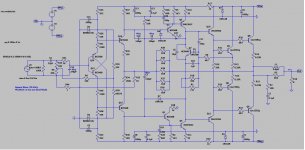
Rallyfinnen,
Thank you for posting your latest schematic. I see the new 10R and 0.1uF (R2/C7) components that you added, may I ask what else you changed or added to help stabilize you amp?
Thanks
Bob
Thank you for posting your latest schematic. I see the new 10R and 0.1uF (R2/C7) components that you added, may I ask what else you changed or added to help stabilize you amp?
Thanks
Bob
- Home
- Amplifiers
- Solid State
- Hifisonix kx-Amplifier