@Jarrodhaas – thank you for more detail. This is a very interesting DML implementation and well done with building this. It’s like making a cello or double bass.
Someone asked me once, if I can find the video with the dug out center of the EPS board DML to attach it here. Here it is.
Also, here is a composer playing wooden DMLs.
Is that your video? Clever use of the attenuator on the cone speaker.
The video of the wooden DMLs is interesting. The panels certainly defy the conventions for "optimal" L/W dimensions, and the exciters for node placement. They look to be fairly thick, too. It was interesting to hear him break down the differences in tone between the maple and the cedar. We're so used to using thin ply, it makes me wonder what the sound and sensitivity are like on solid hardwoods. I guess when you're doing an array of them like he did you can offset low sensitivity with sheer number of drivers.
Last edited:
Here's a horrible demo video if anyone is interested.
DIY 3mm Plywood DML Speakers - YouTube
Cool. I'm assuming that you used a cnc machine to get the pattern. Is it functional or just decorative?
Also very fascinated about the whizzers. I like the symmetry of the panels but did you consider doing them off-center so you could place the exciter on a 2/5, 3/5 node? Do you have REW measurements or at least subjective input as to the impact they have? I'm assuming you did an A/B comparison between a panel with and a panel without.
Last edited:
Not mine. From the 'net. I promised to give the link, if I found it again. 🙂Is that your video?
About the timber planks, that composer Giorgio Magnanensi works in Vancouver, B.C. He plays on timber with his fingers.
An interesting photo here, where he and his colleague play.
Last edited:
Not mine. From the 'net. I promised to give the link, if I found it again. 🙂
About the timber planks,that composer Giorgio Magnanensi lives in Vancouver, B.C. He plays on timber with his fingers.
Yeah, just a stone's throw away. I doubt the wife would be interested in carving out time to meet with him, whenever our next weekend trip up there might be.
^^
If you do, you might meet lot of interesting people, and those who had heard his wooden resonators. You might be able to hear the resonators live. 🙂
His knowledge on wooden speakers might help.
If you do, you might meet lot of interesting people, and those who had heard his wooden resonators. You might be able to hear the resonators live. 🙂
His knowledge on wooden speakers might help.
Last edited:
I made some DML's long ago. Every once in a while I see somebody bring up a picture of my old DML speakers, makes me smile. Anyway, I experimented at the time with different shapes of foam. The vertical rod shape seemed ideal because it required less floor space. As I recall, the results were very poor. While DML's do not radiate the same way as others, I think the vertical foam rod failed because I didn't have enough surface area inline with the driver's most potent direction.
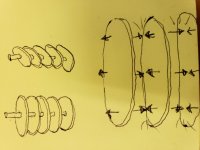
I suspect a better idea would have been to have a thin shaft with many rings emanating from it. To equal the same surface area as a 36"x36" panel, a 1" shaft would need twelve 6" rings (math not guaranteed). You get the point, there is a way to minimize the footprint and maintain/increase surface area. The obvious downside will be earlier cancellation of low frequencies. It's just an idea to improve upon a past failure. It would be pretty easy to build. Cut out rings, slide them down the shaft, attach shaft to driver, and build base around upfiring driver. Omnidirectional is not a problem for DML, in my opinion.
I suspect a better idea would have been to have a thin shaft with many rings emanating from it. To equal the same surface area as a 36"x36" panel, a 1" shaft would need twelve 6" rings (math not guaranteed). You get the point, there is a way to minimize the footprint and maintain/increase surface area. The obvious downside will be earlier cancellation of low frequencies. It's just an idea to improve upon a past failure. It would be pretty easy to build. Cut out rings, slide them down the shaft, attach shaft to driver, and build base around upfiring driver. Omnidirectional is not a problem for DML, in my opinion.
I made some DML's long ago. Every once in a while I see somebody bring up a picture of my old DML speakers, makes me smile. Anyway, I experimented at the time with different shapes of foam. The vertical rod shape seemed ideal because it required less floor space. As I recall, the results were very poor. While DML's do not radiate the same way as others, I think the vertical foam rod failed because I didn't have enough surface area inline with the driver's most potent direction. And since the majority of the sound radiates from the face of the surface, not the edge, you wouldn't get much of anything away from the DML itself.
I suspect a better idea would have been to have a thin shaft with many rings emanating from it. To equal the same surface area as a 36"x36" panel, a 1" shaft would need twelve 6" rings (math not guaranteed). You get the point, there is a way to minimize the footprint and maintain/increase surface area. The obvious downside will be earlier cancellation of low frequencies. It's just an idea to improve upon a past failure. It would be pretty easy to build. Cut out rings, slide them down the shaft, attach shaft to driver, and build base around upfiring driver. Omnidirectional is not a problem for DML, in my opinion.
By this concept, if I'm understanding it correctly (see attachment), wouldn't a corkscrew/auger design make more sense than a bunch of discs spaced out on a shaft? You would get more continual surface area by having one spiral fin vs many wafers, which would mimic a larger single panel. The issue I see here with either design, besides the fact that the facing surfaces aren't projecting sound into the room because the edges are what are facing outwards, and sound wave clash between panels. The sound emanating from both facets of each layer would meet with the sound from the adjacent facing surfaces and it would probably lead to cancelation or at least some unwanted resonances.
Attachments
Last edited:
By this concept, if I'm understanding it correctly (see attachment), wouldn't a corkscrew/auger design make more sense than a bunch of discs spaced out on a shaft? You would get more continual surface area by having one spiral fin vs many wafers, which would mimic a larger single panel. The issue I see here with either design, besides the fact that the facing surfaces aren't projecting sound into the room because the edges are what are facing outwards, and sound wave clash between panels. The sound emanating from both facets of each layer would meet with the sound from the adjacent facing surfaces and it would probably lead to cancelation or at least some unwanted resonances.
Agreed on all fronts. The spiral design seems harder to pull off just for purpose of testing. Less of larger fins also would reduce cancellations/interactions... though the small footprint benefit starts to get lost. There’s lots of things that could be tried: oval wafers, offsetting/staggering wafers, mixing materials, a Christmas tree shape, etc. Standard logic doesn’t always apply to DML. So that is why it may be worth testing—could prove useful in some way.
Last edited:
What might be interesting is to attach a driver to a guitar and play some acoustical guitar music.
By this concept, if I'm understanding it correctly (see attachment), wouldn't a corkscrew/auger design make more sense than a bunch of discs spaced out on a shaft? You would get more continual surface area by having one spiral fin vs many wafers, which would mimic a larger single panel. The issue I see here with either design, besides the fact that the facing surfaces aren't projecting sound into the room because the edges are what are facing outwards, and sound wave clash between panels. The sound emanating from both facets of each layer would meet with the sound from the adjacent facing surfaces and it would probably lead to cancelation or at least some unwanted resonances.
Agreed on all fronts. The spiral design seems harder to pull off just for purpose of testing. Less of larger fins also would reduce cancellations/interactions... though the small footprint benefit starts to get lost. There’s lots of things that could be tried: oval wafers, offsetting/staggering wafers, mixing materials, a Christmas tree shape, etc. Standard logic doesn’t always apply to DML. So that is why it may be worth testing—could prove useful in some way.
Looking at it a different way, the entire speaker is a cone/whizzers. The layers are moving in unison theoretically. Having a whizzer (or many whizzers in this case) doesn't result in phase cancellation that I am aware of. Cube Audio's F8 Neo and F10's employ a similar mechanical concept. The wafers are Voltron. Sure, this is a wild concept and might be total trash.
Looking at it a different way, the entire speaker is a cone/whizzers. The layers are moving in unison theoretically. Having a whizzer (or many whizzers in this case) doesn't result in phase cancellation that I am aware of. Cube Audio's F8 Neo and F10's employ a similar mechanical concept. The wafers are Voltron. Sure, this is a wild concept and might be total trash.
In other words, it is more than just pistonic motion.
Hi chdsl,
My take is the DML concept is that when one excites the substrate with the exciter two waves are being generated a "Pistonic wave" and a shear or tangential wave . The later one is the most important since it generates the Distributive Modes in the substrate.
What one needs todo is to have the exciter couple most of its anergy into the shear wave rather than the pistonic wave. This is what I think is most often over looked in this technology. Just my thought...
Cheers
Steve
^^
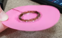
Paste a coil on the panel, connect it to the sound (music) source and bring a magnet near the coil, the panel would give out music. What would happen, if the coil is unwound and pasted on its surface in a large spiral, and then bringing a magnet near it? If music happens, then you could make a hole in the middle of the panel, and fix the magnet permanently (to the frame or to the panel). Fix the panel on a frame, maybe with some soft material.
Paste a coil on the panel, connect it to the sound (music) source and bring a magnet near the coil, the panel would give out music. What would happen, if the coil is unwound and pasted on its surface in a large spiral, and then bringing a magnet near it? If music happens, then you could make a hole in the middle of the panel, and fix the magnet permanently (to the frame or to the panel). Fix the panel on a frame, maybe with some soft material.
Attachments
Cool. I'm assuming that you used a cnc machine to get the pattern. Is it functional or just decorative?
Also very fascinated about the whizzers. I like the symmetry of the panels but did you consider doing them off-center so you could place the exciter on a 2/5, 3/5 node? Do you have REW measurements or at least subjective input as to the impact they have? I'm assuming you did an A/B comparison between a panel with and a panel without.
Thank you, correct everything was cnc and lasered the pattern was just a decorative way to make it easier for me to align everything.
I moved the exciter around a bit and personally on these small panels it sounded better closer to the centre, on bigger panels I would still do 3/5.
As for the whizzers, well they are still a bit of an experiment. They definitely boost the spl and highs but it can start getting tinny the bigger it gets.
From my last post I reduced the size another 10-20% and changed to a carbon fibre pla cone that's tons stiffer and I like it a lot more now. Next I'll be experimenting with different whizzer designs.
Attachments

Thank you, correct everything was cnc and lasered the pattern was just a decorative way to make it easier for me to align everything.
I moved the exciter around a bit and personally on these small panels it sounded better closer to the centre, on bigger panels I would still do 3/5.
As for the whizzers, well they are still a bit of an experiment. They definitely boost the spl and highs but it can start getting tinny the bigger it gets.
From my last post I reduced the size another 10-20% and changed to a carbon fibre pla cone that's tons stiffer and I like it a lot more now. Next I'll be experimenting with different whizzer designs.
Very cool. I envy the equipment and materials you have to work with. The black CF cones look much nicer than the white ones as well. Makes me start wondering about the viability of making simple paper whizzer. How are you attaching yours? I mean, I'm guessing there is a flare at the base that sits flat against the panel, but what adhesive are you using?
Last edited:
As requested here's a clip of only the panels playing, unfortunately still recorded on my phone... Next I need to invest in a proper mic!
3mm Plywood DML Test - YouTube
3mm Plywood DML Test - YouTube
As requested here's a clip of only the panels playing, unfortunately still recorded on my phone... Next I need to invest in a proper mic!
Nice clean sound. Very clear singer's voice.
The whizzers are acting as tweeters. I always considered that there is more to just pistonic motion in cone drivers, that the cone surface is vibrating, and sending sound at every angle. The whizzers in those standard drivers are without a surround, so vibrate freely, and depending of the material, size, angle etc, they give different sound.
OK, coming back to DMLs, if you have a free thin plywood panel, would you try the Teragaki method in the video in post #2571, to bend it slightly?
- Home
- Loudspeakers
- Full Range
- A Study of DMLs as a Full Range Speaker