When I saw that post about the Teragaki speakers I immediately started looking up info on them.... I'll definitely be making a pair.
If anyone is interested in the Instructable: Plywood DML Speakers : 12 Steps (with Pictures) - Instructables
The force vectors are still axial (equal and opposite reaction), the board response is more evenly distributed as its axial movement is restrained (thus bass falloff).

teragaki
I've done a Teragaki style speaker using foam. Quite simple to build, but poor sound... at least my prototype...
When I saw that post about the Teragaki speakers I immediately started looking up info on them.... I'll definitely be making a pair.
I've done a Teragaki style speaker using foam. Quite simple to build, but poor sound... at least my prototype...
Good question! First a quick explanation of the setup: the exciters are configured so that each side, i.e. one long/short bridge pair (running the direction of the length of the bridges, on the same side of a spline) is a crossed-over high/low channel. So the short bridge plays highs, and the long bridge lows. One amp runs the highs, one the lows, and then there's an active sub CX'd at ~200hz as well.
Jarrodhaas,
Firstly, what a cool and beautiful build! And to have that quality time with your father is priceless for sure. Please keep us posted about your progress!
My question is about the exciter configuration. I must admit I don't quite understand your explanation. I don't understand, for example, what you mean by "one long/short bridge pair.."
But mainly, I'm wondering why you decided to separate the signals into highs and lows? Why not simply run the whole frequency range into all the exciters, and avoid the complication of multiple amps and a crossover? To be clear, I'm not suggesting that I think your approach is wrong, I just want to better understand the basis for your arrangement.
Thanks,
Eric
Not answering for Jarrod but in my recent experimenting I have found that running 2 exciters on a single panel, actively crossed over into low/high divisions seems to get me better FR and fidelity than using single or multiple exciters running at full range. I use dayton 32mm 40 watt exciters for the low end Dayton 25mm 10 watt units for the highs. My theory is that just because something can play full range doesn't mean it excels at doing it, so why not approach it like speakers and let the beefy boys handle low end and the smaller high efficiency units do mids and highs, taking some of the strain off each.
I need to stop jumping into other side experiments and take some REW measurements to see if it's just a placebo effect though.
Last edited:
I've done a Teragaki style speaker using foam. Quite simple to build, but poor sound... at least my prototype...
The exciters on those Teragaki speakers are something else. I have a feeling you would be hard pressed to replicate those panels with off the shelf exciters. I could be wrong, though. The underlying structures also are more complex and take a different approach to mounting and bracing than your average hobbyist DML. I'd love to hear a pair and find out how good they sound.
This is a deep rabbit hole to dive into!
I'd like to mess around with DMLs but I'd also like to avoid the shipping costs and delays from the US. Has anyone found a reasonable source from China? All I have found is
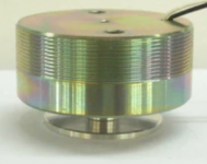
Ths one which is quite a bit heavier and larger then similar 20W Dayton Audio ones. It looks like it has a different mechanism than the smaller ones such as this.
I'd like to mess around with DMLs but I'd also like to avoid the shipping costs and delays from the US. Has anyone found a reasonable source from China? All I have found is
Ths one which is quite a bit heavier and larger then similar 20W Dayton Audio ones. It looks like it has a different mechanism than the smaller ones such as this.
This is a deep rabbit hole to dive into!
I'd like to mess around with DMLs but I'd also like to avoid the shipping costs and delays from the US. Has anyone found a reasonable source from China? All I have found is
Ths one which is quite a bit heavier and larger then similar 20W Dayton Audio ones. It looks like it has a different mechanism than the smaller ones such as this.
Oops, my first post in diy...😱
The first one in my experience the frequency respons is in the highs a bit lacking. IMO more suited for baspanels wich i have one under construction😎. The second type is exellent in FR. I am testing types with framed woodpanels at the moment wich gives the most natural responce IMO.
I have these: Aiyima 2 Stuks Audio Speakers 35/44Mm Vliegtuig Trillingen Speaker Resonance Speaker 15W 4 Ohm Diy Voor home Theater|4 ohm|speaker resonancevibration speaker - AliExpress
Last edited:
^^
What's in the US, are most probably made in China. 🙂 Your neighbour has lot of them. And, much cheaper.
What's in the US, are most probably made in China. 🙂 Your neighbour has lot of them. And, much cheaper.
Yes, there are many in China.
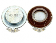
However both your links and my links show that there are roughly two types. One group looks like a small piston. These, at times, talk about specifically horizontal operation and don't show how to attach them (left hand picture). The other type looks closer thinner and more exposed. This type does not have such an obvious piston, doesn't tend to have any mention of horizontal versus vertical in the description and is often shown with a tape type of attachment (right hand picture).
Are there differences between the types?
Attachments
Yes, there are many in China.
However both your links and my links show that there are roughly two types. One group looks like a small piston. These, at times, talk about specifically horizontal operation and don't show how to attach them (left hand picture). The other type looks closer thinner and more exposed. This type does not have such an obvious piston, doesn't tend to have any mention of horizontal versus vertical in the description and is often shown with a tape type of attachment (right hand picture).
Are there differences between the types?
I have both of them 😀 and they work the best if you mount a wooden brace across the frame to support the exciter. The outcome is they produce more spl and a broader FR because this way al the power is going into the panel.
If you dont brace you lose power because the exciter pushes himself away from the panel ergo less power going into the panel loosing spl and FR.
Also framed panels takes care of unwanted resonances! Double win i would say😉. Complete framing is on debate and have to test further...?
The sound difference is as i told before: The thick left one is having a slightly less high frequency output (maybe bass panels?) as the right smaller one (thats the king IMO).
I attach the foot of the exciters to my 4mm plywood with woodlime and the back directly on the brace with hotglue to hold it.
The plywood is already treated in a special way.
First with 70/30 water/woodlime dillution to soak the wood so that the lime is going into the graines and inside of the panel from both sides. When dried/hardened a second layer 30/70 water/woodlime to create a bonding effect with the first layer on the outside. This hole proces is for better propagation of the waves for the sound production from back to front side of the panel. Now i stop rambling

Jarrodhaas,
Firstly, what a cool and beautiful build! And to have that quality time with your father is priceless for sure. Please keep us posted about your progress!
My question is about the exciter configuration. I must admit I don't quite understand your explanation. I don't understand, for example, what you mean by "one long/short bridge pair.."
But mainly, I'm wondering why you decided to separate the signals into highs and lows? Why not simply run the whole frequency range into all the exciters, and avoid the complication of multiple amps and a crossover? To be clear, I'm not suggesting that I think your approach is wrong, I just want to better understand the basis for your arrangement.
Thanks,
Eric
Thanks! working with my Dad and tapping into his expertise was definitely the highlight of the project.
Yeah its a bit difficult to explain! I'll take another run at it: if you look at the photo and were to rotate the soundboard so that the splines on the back run vertically, on each side of the middle spline are 4 exciters for each channel, and each channel has a long and short bridge. The short bridge is for highs, the long for lows. So you end up with a chiastic kind of formation, unlike a standard speaker, which would have the tweeters (usually) up top and the woofers below for each channel.
The main reason I went for that design was because it's the same one used by JMC for their soundboard. I figured that they had probably done a significant amount of RnD, so why not start there. In that case, they use passive components to xOver and perhaps also EQ. I had no idea ahead of time how close to a good foundation we were going to achieve with our build, so I chose an active, bi-amp+sub design to allow for maximum flexibility in controlling the output. This allowed us the best chance of getting to sound good after all the time we spent. If we build another one, I'd possibly pursue passive components to keep things simpler.
I will say that, although the bridges for highs/lows are quite different in size and position, this makes very minimal difference in their frequency characteristics (measured with a umik-1, see attached images. red is short bridges, green is long bridges).
Having built this design, and looking at Opere Sonore's stuff (example attached), I think there's quite a bit of flexibility with the design possibilities. I'm sure it would be possible to get something decent with less exciters and a simpler electronics setup, without having to be a luthier. Being able to fix things with DSP definitely makes the job much more forgiving, thought. It would be hard to get something really tight (e.g. +/- 3db everywhere) without the electronics.
Cheers!
Attachments


Someone asked me once, if I can find the video with the dug out center of the EPS board DML to attach it here. Here it is.
Also, here is a composer playing wooden DMLs.
Yes, I've seen this before -- pretty cool stuff.
All of the videos i've seen of his music have avant garde / minimalist / classical strings type stuff. These would be the most forgiving types of music on a panel design, in my experience. Not sure how well something like this would do for a general listening rig without significant tweaking. I suspect he's more about the aesthetic than a developing a hifi rig though.
I've done a Teragaki style speaker using foam. Quite simple to build, but poor sound... at least my prototype...
Any pictures?
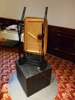
...and looking at Opere Sonore's stuff
In that image, I notice that there are two panels fixed together, the back one appears to be plywood, and the splines look more like Teragaki's. The front is the eye-candy panel, piano wood.
^^
What's in the US, are most probably made in China. 🙂 Your neighbour has lot of them. And, much cheaper.
I would love to get on my soapbox and explain why avoiding Chinese products is an imperative, but this probably isn’t the place. I will say that it looks like Visaton is starting to make exciters. Usually, Visaton drivers are made in Germany... I think.
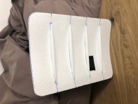
Teragaki style prototype
Here is my attempt. Teragaki inspired, but of course only for bracings, because I've no informations about drivers etc. It took me half an hour for building, but same size, plain board sounded quite better...Experiments will continue, may be with plywood or toneboards
cheers
Any pictures?
Here is my attempt. Teragaki inspired, but of course only for bracings, because I've no informations about drivers etc. It took me half an hour for building, but same size, plain board sounded quite better...Experiments will continue, may be with plywood or toneboards
cheers
Attachments


I've been watching a video about Focal factory tour for last 2 hours. In the first few minutes, you are shown how the speaker's membrane is made. This part might be of interest to the DML DIYers, as we are considering a membrane to be the speaker, flat or otherwise. The membrane is made of 3 layers. It starts from a flat panel, then pushed to the cone shape, a foam panel.
Later, half way through, two engineers are explaining about the speakers, and their parts. They are talking about the membrane, surround etc, and how they react to each other. One can pick some interesting ideas off that talk, especially about the membrane. Btw, no one talks about pistonic motion or mass of air movement, but about the way the membranes and how they work. And, how these membranes are made and why. Vibrations go along the surface.
Here's the video. There's lot of info, also for other projects.
Yeah its a bit difficult to explain! I'll take another run at it....
The main reason I went for that design was because it's the same one used by JMC for their soundboard.
Jarrodhass,
Thanks, now I understand.
Do you recall exactly where you got the information about JMC's transducer arrangement? I've looked at their website in the past for clues about it's design and construction, but I don't recall seeing any details about their transducer arrangement.
Eric
- Home
- Loudspeakers
- Full Range
- A Study of DMLs as a Full Range Speaker