Thebet,
The advantage of having a Spice model is that you can simulate broken components.
The most likely cause that I can find for your problem is that Q128, the MJE15031 is broken.
This happens more than once.
Hans
The advantage of having a Spice model is that you can simulate broken components.
The most likely cause that I can find for your problem is that Q128, the MJE15031 is broken.
This happens more than once.
Hans
Thanks for .asc Hans 🙂 it saved me a job 😀
OK, lets try and see if we can make some sense from this......
OK, lets try and see if we can make some sense from this......
So the references are good (Zeners) and the raw supplies good.
Resistors can not be reliably measured in circuit due to interactions and residual voltages upsetting the DVM reading. I think R151,153 and the preset need checking out of circuit. You only need lift one end of R151 and R154 to do this. All three can then be measured accurately.
I think that has to be done first 🙂
Also Han's suspicion of the transistor (and perhaps others) is worth exploring. A good check is to measure the base/emitter voltage while the circuit is on but you must be super careful because one slip could cause damage.
All B-E junctions should be dropping around 600 to 700 millivolts approximately with the base the more positive for the NPN devices and vice versa for the PNP's.
Another way to attack this is for you to carefully measure all voltages on all transistors in that half of the regulator and post the results. That would show any anomalies up.
Post in the form:
Q115
E=
B=
C=
And so on 🙂
But check those resistors first.
Hi Thebet,
I've put your supply in LTSpice, hoping that you can use this.
In the first image below, I have shown the power supply rejection ratio, assuming that on your Amp board there is still a 330uF connected to Vreg.
Looking at the graph, I'm not really impressed by this PSRR.
When removing C113, it becomes already a lot better, see second image.
Anyhow, you can use the Sim file and compare all the voltages in your Amp.
Hans
Hi Hans,
thx for working so much for my problem.
There is no 330uf capacitor in amp board. But there is one 150uf in the VOLTAGE GAIN board connected to -Vreg (and one more connected to +Vreg).
These capacitors looked OK, but i have changed them with 470uf/160V Nichicon (which i had in Lab).
Let's see...
Do you have a scope ?
In those cases as you mention, there is in most case an oscillation going on, making your DC measurements rather useless.
Hans
I do have a Picoscope.
Last time i used it, was many years ago.... 😕
I have to check if i still have the relative software somewhere (laptops changed many times since then).
The funny thing is, that i 'm able to recall a similar problem with another amplifier, many years ago, but i don't remember what the problem was...
My memory is not that sharp as it used to be... aging....

Anyway, my opinion is also that a transistor is the problem, i will start with MJE1503x....
So the references are good (Zeners) and the raw supplies good.
Resistors can not be reliably measured in circuit due to interactions and residual voltages upsetting the DVM reading. I think R151,153 and the preset need checking out of circuit. You only need lift one end of R151 and R154 to do this. All three can then be measured accurately.
I think that has to be done first 🙂
I will do it....
Also Han's suspicion of the transistor (and perhaps others) is worth exploring. A good check is to measure the base/emitter voltage while the circuit is on but you must be super careful because one slip could cause damage.
Too risky!!! as i said age makes my hands not so stable....🙂
Theodore
Hi Hans,
thx for working so much for my problem.
There is no 330uf capacitor in amp board. But there is one 150uf in the VOLTAGE GAIN board connected to -Vreg (and one more connected to +Vreg).
These capacitors looked OK, but i have changed them with 470uf/160V Nichicon (which i had in Lab).
Let's see...
1) Did you change those caps before or after the problems with Vreg- ?
Problem is that with a cap that is 3 times as large, the inrush current at start up is also 3 times as large, an accident waiting to happen since there is no current limiter in the power supply !
2) Do you also have a circuit diagram of what you call the voltage gain board ?
Hans
1) Did you change those caps before or after the problems with Vreg- ?
Problem is that with a cap that is 3 times as large, the inrush current at start up is also 3 times as large, an accident waiting to happen since there is no current limiter in the power supply !
After the problem with -Vreg!
Tried to exclude any potential causes.
2) Do you also have a circuit diagram of what you call the voltage gain board ?
Yes, attached.
C65 and C73 are what i meant.
C1, C2 (68uf/63V) have also be changed (ML recommends this upgrade) with Panasonic caps, same value.
C15, C18, C30, C58 (10nf/160V) have also be changed (ML recommendation).
All changes have been done AFTER the problem with no bias and no adjustment in -Vreg.
By the way, i just changed the Q128 with new one, (and the Q126 - it was next to it, just in case). Their measurements were fine, but i did it just in case (well the old ones were Motorola, the new Multicomp - not sure if they are of the same quality).
However, there was NO change - still not able to adjust the -Vreg.
Theo
That's a shame.I just changed the Q128 with new one, (and the Q126 - it was next to it, just in case). Their measurements were fine, but i did it just in case (well the old ones were Motorola, the new Multicomp - not sure if they are of the same quality).
However, there was NO change - still not able to adjust the -Vreg.
Theo
You will have to look in the right side that's being fed by Vprereg-.
The left part seems ok so far.
Compare the voltages with the positive side, or with the LTSpice model I sent you.
I have another problem with this circuit diagram.
When I attach the 330n at the output, the regulator starts oscillating with an amplitude of 7 volt pk-pk.
When adding the 470uF that you use, oscillation goes on but now with 20mV pk-pk.
This is something to look at when everything is O.K. again.
But for now, do you have a scope to check whether Vreg- is oscillating ?
Hans
Last edited:
Thebe,
A bit surprised by the oscillation problem, I found the perfect solution just in case you experience the same symptoms.
Q108 and Q121 have a 2n2+249R network from base to collector.
When adding this same 2n2+249R network to Q109 and Q122, also from base to collector, the system becomes unconditional stable, as well with the 330nF alone and also with the added 470uF.
Hans
Sorry for my late reply guys, i had to work a bit.... blac friday! 😉
...Still i'm extremely impressed with your assistance 🙂 thank you very much.
In our case now:
Hans pls do not forget that this circuit was working perfectly in the past. For many years... I believe we should stay focused on the original ML diagram.
Otherwise it is not ML!
Maybe i'm wrong but this is an ML No 335. Very good sounding amplifier - probably one of the best Mark Levinson ever made...
To be clear: I suppose you meant Q108 and Q122... relatively Q109 and Q124; please clarify!!!
To be honest: i 'feel' that the problem is something simplier... somewhere.... hidden under my eyes!!!!!!! as i said all components seem and measure fine. I don't understand it!!!😱
I have not checked only the small TO92 transistors...
Tomorrow i will go to buy a ML 336 (christmas present for myself-absolutely original device 🙄)
So, probably i can check again on the problem on Monday, but i will be here for further discussion...
I think that finally i have to remove the Current Gain board (the big one) from heatsink to check what is going on underneath...
hmm you believe the problem is on the right side.... perhaps.... but this side is the so called REGULATOR BIAS and still i can adjust it to the recommended value. What i can not adjust is the left part which should go to -115 V but only reach -103/-104V and then drops again. strange...
This is logical Hans; we are talking for local smoothing. The bigger capacitance, the better... (still there is a max value but this is another story)
But please tryin your convenience a simulation with 150uf caps. As the original circuit. thx.
Well, we should not forget that the caps i removed (150uf/150V) were OK. And the device was working in the past.
Theodore
...Still i'm extremely impressed with your assistance 🙂 thank you very much.
In our case now:
A bit surprised by the oscillation problem, I found the perfect solution just in case you experience the same symptoms.
Q108 and Q121 have a 2n2+249R network from base to collector.
When adding this same 2n2+249R network to Q109 and Q122, also from base to collector, the system becomes unconditional stable, as well with the 330nF alone and also with the added 470uF.
Hans pls do not forget that this circuit was working perfectly in the past. For many years... I believe we should stay focused on the original ML diagram.
Otherwise it is not ML!
Maybe i'm wrong but this is an ML No 335. Very good sounding amplifier - probably one of the best Mark Levinson ever made...
To be clear: I suppose you meant Q108 and Q122... relatively Q109 and Q124; please clarify!!!
To be honest: i 'feel' that the problem is something simplier... somewhere.... hidden under my eyes!!!!!!! as i said all components seem and measure fine. I don't understand it!!!😱
I have not checked only the small TO92 transistors...
Tomorrow i will go to buy a ML 336 (christmas present for myself-absolutely original device 🙄)
So, probably i can check again on the problem on Monday, but i will be here for further discussion...
I think that finally i have to remove the Current Gain board (the big one) from heatsink to check what is going on underneath...
You will have to look in the right side that's being fed by Vprereg-.
The left part seems ok so far.
Compare the voltages with the positive side, or with the LTSpice model I sent you.
hmm you believe the problem is on the right side.... perhaps.... but this side is the so called REGULATOR BIAS and still i can adjust it to the recommended value. What i can not adjust is the left part which should go to -115 V but only reach -103/-104V and then drops again. strange...
I have another problem with this circuit diagram.
When I attach the 330n at the output, the regulator starts oscillating with an amplitude of 7 volt pk-pk.
When adding the 470uF that you use, oscillation goes on but now with 20mV pk-pk.
This is something to look at when everything is O.K. again.
This is logical Hans; we are talking for local smoothing. The bigger capacitance, the better... (still there is a max value but this is another story)
But please tryin your convenience a simulation with 150uf caps. As the original circuit. thx.
Well, we should not forget that the caps i removed (150uf/150V) were OK. And the device was working in the past.
Yes mooly, I have also noticed that.... very uncommon design nowadays... 🙂They like using lots of diodes... reminds me of Philips
Theodore
Thebe,
A bit surprised by the oscillation problem, I found the perfect solution just in case you experience the same symptoms.
Q108 and Q121 have a 2n2+249R network from base to collector.
When adding this same 2n2+249R network to Q109 and Q122, also from base to collector, the system becomes unconditional stable, as well with the 330nF alone and also with the added 470uF.
Hans
Even without scope, i can measure an oscillation problem with a digital voltmeter.... it goes up and down within few mV; this is clearly oscillation.
The question is why....
Theodore
So the references are good (Zeners) and the raw supplies good.
Resistors can not be reliably measured in circuit due to interactions and residual voltages upsetting the DVM reading. I think R151,153 and the preset need checking out of circuit. You only need lift one end of R151 and R154 to do this. All three can then be measured accurately.
I think that has to be done first 🙂
Well, I forgot to mention that i have measured R151,R153, R154 out of the circuit (de-soldering one pin of R154 is enough).
They are f**** correct!! I don;t know if they change from temperature, but cold are exactly the mentioned values!!! amazing?
Theodore
Theodore
They had to be checked 🙂
Lets go back to absolute basics... please measure these points and record what you actually have. The resistors are all low value and you can measure on either end.
1/ You have -60v applied to the base of Q115. This is the reference voltage. You can measure this on R141.
2/ When you set the output to its maximum (lets say -103 volt) what voltage do you have on R147? This is the base of Q116.
The two voltages should be equal when operating normally (no matter what the voltage is set to) but lets see what you actually have.
3/ What is the voltage on R145?
4/ What is the voltage on R146?
These should be similar as well.
Lets go back to absolute basics... please measure these points and record what you actually have. The resistors are all low value and you can measure on either end.
Good morning!
pls give me some time....i will check these values on Monday (first thing in the morning) 🙂
I was thinking (during the night) that the relays of these boards (voltage regulator, Current gain (both in the same PCB), Voltage Gain (the other diagram, another PCB)) are controlled from another circuit, called VSMB, at the bottom of amplifier. On this board there are all protection circuits, as well as the soft start circuit (similar to what ML 27.5 has).
Probably something goes wrong there? I will send the diagram on Monday (thx to Oscar, another member in forum, i have nearly all schematics).
Maybe you can see something i don't see...
Have a glorious Sunday!
Theodore
No I meant Q106/Q121 (with network) versus Q108/Q122 (without network) , these are MJE1503x transistors.Hans pls do not forget that this circuit was working perfectly in the past. For many years... I believe we should stay focused on the original ML diagram.
Otherwise it is not ML!
Maybe i'm wrong but this is an ML No 335. Very good sounding amplifier - probably one of the best Mark Levinson ever made...
To be clear: I suppose you meant Q108 and Q122... relatively Q109 and Q124; please clarify!!!
On the printout the numbers where a bit difficult to read, sorry for that confusion.
And just said, only for the case you experience oscillation problems, you have this solution, because stability is definitely on the edge.
And with the original 150uF, oscillation is of course even a bit worse.
So don't change anything that is O.K., but it's good to have a remedy at hand just in case.
Maybe, but you have checked the Vprereg to be ca -130Volt, and according to the circuit diagram, nothing from outside can prevent the Vreg-to become -115V, just as the Vreg+ is correctly +115Volt.To be honest: i 'feel' that the problem is something simplier... somewhere.... hidden under my eyes!!!!!!! as i said all components seem and measure fine. I don't understand it!!!😱
I have not checked only the small TO92 transistors...
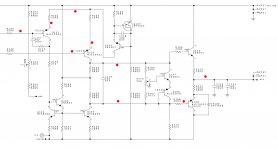
So I agree with Mooly that ik makes sense to measure the voltage on both sides of R147 with reference to gnd, while you turn the pot R153 to confirm that this voltage stays at a stable -60 Volt.
When that's O.K., concentrate on the right half, see image below what I mean with that.
Try to measure the voltages at the red dots.
When reporting this back, we will try to help you finding the problem.
Hans
Attachments
Thebe,
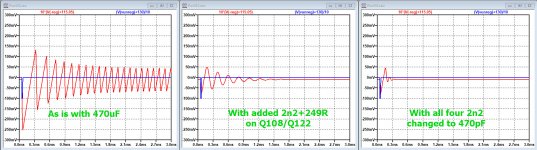
Just to inform you what a simulation with LTSpice tells, here 3 images of the voltage on the Vreg holding your 470uF, when a 1 Volt spike is induced on Vprereg through the mains, an absolute every day's thing to happen.
Don't feel forced to change anything, it is just to give you some insight in things.
1) The first graph shows that a voltage spike excites the regulator into a permanent oscillation
The voltage is magnified in the image by a factor 10, so the oscillation signal has a real amplitude of 10mV pk-pk.
2) In the next graph a second network of 2n2+249R has been placed over Q108 and Q122.
The excited response now dies after ca 2msec and has a much friendlier frequency content without the earlier sharp edges.
The system is now unconditional stable.
3) Now in the third graph all four 2n2 caps have been replaced by 470pF caps, resulting in an even faster recovery from the generated voltage spike in Vprereg.
Hans
Attachments
- Home
- Amplifiers
- Solid State
- Mark Levinson No 335 - NO Bias in one channel / NEED HELP