No, IC voltage regulators are effective in regulation and filtering at the same level.IC voltage regulators main function is to regulate voltage 😱 and they actually do this quite well.
What they instead do not do very well is to suppress ripple.
For this job very effective are capacitance multipliers. ,
Any 78xx IC has at least 60 dB (1000) filtering effect at 100/120 Hz.
Any LM317 IC has a 60-80 dB (1000-10000) filtering effect at 100/120 Hz.
But try to get the same efficiency at this frequency from a capacitance multiplier (without a MOSFET and a large capacitor)...
We have to say that they differ at higher frequencies. The higher the frequency the higher the efficiency (I mean a filtering effect) of a capacitance multiplier is. And the opposite for a regulator IC.
Last edited:
Hi ! thank you so much again and very kind to you to follow my journey at the discovery of power supply regulators.No, IC voltage regulators are effective in regulation and filtering at the same level.
Any 78xx IC has at least 60 dB (1000) filtering effect at 100/120 Hz.
Any LM317 IC has a 60-80 dB (1000-10000) filtering effect at 100/120 Hz.
Yes i have looked at the datasheets and the ICs psrr is quite good at lower HZ. And for some boutique recent ICs they are also quite good at higher Hz but also quite expensive and with Iout a little limited ? ok that i guess can be boosted ...
But it is not for me a question this one or that one ... but why not both in series ? i do not know which one first and which one after ...
thanks ! so the CM are not that great at lower Hz. I did not know this.But try to get the same efficiency at this frequency from a capacitance multiplier ... (without a MOSFET and a large capacitor)...
About mosftes being the device of choice this mirrors exactly what i am reading Their virtue is the very high DC current gain ? or at least they act as very high DC current gain devices.
Even if darlingtons are not less interesting to me ... actually i love darlington. They provide DC current gains of the order of 500 ... it is a lot. Have i to use them ? they cost nothing ...
And by the way .... i have not seen one CM circuit employing mosfets 😕😕😕 what is going on ?
Without any schematic reference it is difficult to me to start doing something .. i have no clue about parts selection
The only mosfet i know is the irf610 i had in a bride of zen preamp. My guess now is that it could use with great effects also in a CM circuit ?
I am thinking of a two stage regulator using one mosfet per stage and in one of the two a zener to set the voltage, maybe in the last stage before the circuit to power (only line preamps here. I have no other interest With voltage up to 60V and current up to let's say 0.5A max ... but usually much less)
thank you very very much indeed again for this very important advice.We have to say that they differ at higher frequencies. The higher the frequency the higher the efficiency (I mean a filtering effect) of a capacitance multiplier is. And the opposite for a regulator IC.
It is very clear to me now that the two circuits are complementary and both should be used together.
Now IC voltage regulators are very handy indeed, expecially fixed voltage one. But what about discrete regulators ? do they also provide lower psrr at lower HZ than IC regulators ?
Anyway ... this last doubt aside i am quite set on the idea of using after the 1st rectification stage a mosfet based capacitance multiplier circuit and then a IC regulator or a discrete regulator ... will see.
The search is on to find schematics of mosfet based capacitance multiplier (or also darlington. I am fine with dc current gain of only 500)
If i can make a very silent psu i am done. Because then i could put the blame only on the preamp circuit.
I have alreayd a guinea pig preamp to mod in the psu It has fixed IC regulators I am seriously thinking to place a CM circuit upstream the IC regulation stage. Really seriously.
Thank a lot again. 🙂
Last edited:
The VGS of a MOSFET usually spreads more than the VBE of a bipolar transistor and (due to its smaller gm ro product) the ripple rejection of a MOSFET source follower is usually less than that of a bipolar transistor. Maybe that's why you don't see them much.
The VGS of a MOSFET usually spreads more than the VBE of a bipolar transistor and (due to its smaller gm ro product) the ripple rejection of a MOSFET source follower is usually less than that of a bipolar transistor. Maybe that's why you don't see them much
Hi ! thank you very much indeed for the kind and valuable advice.
Actually i have not seen them at all 😀
Well ... out mosfets and enter ... darlingtons ?
I have seen circuits with two or more bjts in series ... i am attaching one as an example
Why not using darlington instead for a capacitance multiplier ? they are already very high dc current gain devices .... i guess 500 is more than enough 🙄
Attachments

I can't think of any reason not to use Darlington transistors. Actually the schematic shows a Darlington circuit, just not integrated into one device.
I can't think of any reason not to use Darlington transistors. Actually the schematic shows a Darlington circuit, just not integrated into one device
Hi ! great and thank you very much again. These days i am surfing this section of the forum looking for regulators projects.
Some are very very complex. And strangely enough often i see them not backed by measurements. i guess that their performance are extimated with some sim SW ?
Anyway ... i am quite settled now. I will put this cap multiplier circuit before a final IC based regulation stage.
If i understand well the CM circuit acts as an active low pass filter ? maybe the slope/cut Hz are not enough to provide great psrr also at low Hz, remaining very very good indeed at higher Hz ?
All this my rambling is due first to ignorance second to a lack of a nice spectrum analyzer.
For instance i am playing now with some smps ... a check with a wide band spectrum analyzer would provide me with a picture of their noise floor.
How the noise is distributed along the band.
I understand that a smps switch at around let's say 100kHz ... if the noise at 100Hz is very very low i could do with just a cap multiplier circuit and be done with that. Instead i guess linear power supplies should have most of their noise at lower Hz ? considering the grid frequency
Sometimes i ask some excellent designers here if they have checked their prototype with a spectrum analyzer and they answer ... i do not have any 😱 like a doctor without a stetoscope
Now i am in very bad moment with my job ... but when i will retire the 1st thing i will do is to set up a cheap but decent noise analyzer system.
Noise is not music ... lowering the noise the details jump out in an exciting way. It is impressive with some live recordings in particular.
I will buy some components and play with them.
Thanks a lot again.
Last edited:
You could maybe start with a modern digital scope. Many come with FFT analyzers these days and that already gets you somewhere.
Apart from that I don't see the point why a discrete version of anything would be "better" than an IC version. Just all the extra parasitics and extra cost of a discrete something isn't worth it.
Apart from that I don't see the point why a discrete version of anything would be "better" than an IC version. Just all the extra parasitics and extra cost of a discrete something isn't worth it.
For a start, you may use your soundcard and the free REW.All this my rambling is due first to ignorance second to a lack of a nice spectrum analyzer.
I’ve posted a spectrum at this same thread
Are you really fine with IC voltage regulators ?
George
Hi ! thank you very much indeed for your kind and helpful advice. I have a situation here that does not allow me to tackle seriously the issue ... for the moment. But this a life long hobby for me. I am very willing to involve myself more when time will allow. Anyway i am still undecided between the sound card + pc + SW route or the standalone instrument.You could maybe start with a modern digital scope. Many come with FFT analyzers these days and that already gets you somewhere.
Just to get an idea of the cost to face could you recommend me a standalone digital scope with FFT feature with a good quality/price ratio ?
I understand that proper spectrum analyzers come very expensive. But they are my dream ... i have never used one 😱 but for me it is by far the most fascinating instrument. When i see noise/distortion spectra i am in awe.
To see what i even cannot listen ... fascinating.
thanks for the advice. After reading how good IC regulators psrr is in the lower part of the audio range and how bad are cap multiplier i have the feeling that the best compromise would be a two stages solution using both.Apart from that I don't see the point why a discrete version of anything would be "better" than an IC version. Just all the extra parasitics and extra cost of a discrete something isn't worth it
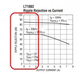
Nevertheless lookinb with more attention 😱 to the datasheets .... i am noticing that some IC regulators are not that bad in the entire audio range (example attached).
Problem is that i really like to start upstream with a smps and then decrease the voltage and stop its noise. And their noise is a lot out of the audio range. So it seems that a cap multiplier is really needed. I mean ... to get rid of the ultrasonic noise from the smps.
Attachments
Hi ! thanks a lot for the very valuable advice. May i ask what are you using ? i have not understood completely what benefits could provide a standalone solution. For sure it should be more expensiveFor a start, you may use your soundcard and the free REW.
I’ve posted a spectrum at this same thread
Are you really fine with IC voltage regulators ?
George
and i have also another question ... is the out of audio band noise very nasty ? what issues could it generate ?
I love to start with a smps ... also because i have seen noise spectra of psu based on smps properly filtered and they are completely flat and extremely low in level. I guess filtering is key for this because from the datasheets i see that an average noise (wideband 🙄) of an OTS smps is around 100-200mV ... but i did not see an actual noise spectrum of an unfiltered smps. I would be very curious to see it.
In the meantime i will try to get more information on these cap multiplier circuits. But again to check their performance i need some kind of instrument ... maybe a very textbook circuit based on a single darlington could be a great HF noise suppressor.
Thanks a lot again.
Last edited:
It all depends on the application. In a DAC, out-of-band noise that crosstalks to the clock or the voltage reference can convert out-of-band noise or aliases into the audio band. In an amplifier, out-of-band noise on the supply usually doesn't do much harm unless it is very stong.
Thanks a lot for the very helpful advice. Personally i wonder why smps at least for low power equipment are not so popular. 🙄It all depends on the application.
In a DAC, out-of-band noise that crosstalks to the clock or the voltage reference can convert out-of-band noise or aliases into the audio band. In an amplifier, out-of-band noise on the supply usually doesn't do much harm unless it is very stong
I was looking inside a professional clock generator .... it uses a smps to power the circuits. I think that good filtering is key.
But without an instrument i am just rambling and please excuse me for this 😱
I am experiencing a very strong frustration because if i do not see and do not believe
I have to put more effort to set up a small lab bench. I hope to be able to do this during the next holidays. For sure when i will retire 🙂
I use an an external USB soundcard, an older model from Creative: E-MU 0404. It was a generous gift from member mkc.May i ask what are you using ?
It has 1MOhm differential inputs and can work at 192kHz sample rate, therefore it can read up to 96kHz.
REW ( REW - Room EQ Wizard Room Acoustics Software ) is an excellent free software (it’s developer maintains and upgrades it constantly, he deserves our donation). Among other many features, it does FFT and if you calibrate it properly, the oscilloscope function is very good.
The electric noise at the output terminals of SMPS can be filtered quite easily and effectively.and i have also another question ... is the out of audio band noise very nasty ? what issues could it generate ?
The problem with SMPS is IMO the radiated noise. If you move around the SMPS a simple wire loop and monitor with an oscilloscope, you will see that the switching elements and the transformers emit a lot of HF fast rising pulses.
The SMPS has to be kept at a distance from sensitive audio circuits (and oriented properly toward them) and/or enclosure shielded. Else, some/all of radiated EMF will be picked up by the nearby circuits and cabling.
George
Thanks a lot again. I read about this card and its excellent qualities.I use an an external USB soundcard, an older model from Creative: E-MU 0404. It was a generous gift from member mkc...
Unfortunately it is an obsolete unit with no drivers for win 10 that is what i am using
I will try the SW for sure.
you mean with a cap multiplier for instance ? or passively ?The electric noise at the output terminals of SMPS can be filtered quite easily and effectively
Thanks ! i wonder if putting it in a metallic box could help to block radiations... The problem with SMPS is IMO the radiated noise. ...
George
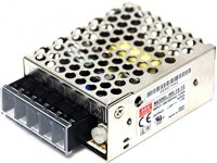
I will search about this. I am using the kind in the picture
Attachments
There are available drivers good for win10. I use it with Win10 (64bit) as well.with no drivers for win 10 that is what i am using
Both work.you mean with a cap multiplier for instance ? or passively ?
Make a 1cm diam loop (2-3 turns), connect it to your soundcard input with a coaxial cable and monitor the waveform (and FFT) at various locations of the probe and distances from the SMPS.I will search about this.
George
i was wrong. Actually i had one but i had issues with drivers some years ago.There are available drivers good for win10. I use it with Win10 (64bit) as well.
But i will check better
Both work.

thanks again. They must be shielded in some ways. I understand that steel is the material to use. And i will ground also the case for safety. The smps frame is grounded. I checked. Thanks a lot again. 🙂Make a 1cm diam loop (2-3 turns), connect it to your soundcard input with a coaxial cable and monitor the waveform (and FFT) at various locations of the probe and distances from the SMPS.
George
There's a passive filter project by Mark Johnson on this site -- if I wasn't so lazy I'd try to find the link for you. Even though it is aimed at *power brick*, inline power supplies, it would surely provide the filtering you need. A lot of engineering has been put into it, and he gives away the design. Might be worth checking into.
Just my opinion, but it makes more sense to make war on a noise / EMI problem once you know for sure that you have it, than to set out to *minimize* it beforehand. Probably even more true today, in this era of -100dB-plus noise-floor gear, than it was just a few years ago.
Cheers
Just my opinion, but it makes more sense to make war on a noise / EMI problem once you know for sure that you have it, than to set out to *minimize* it beforehand. Probably even more true today, in this era of -100dB-plus noise-floor gear, than it was just a few years ago.
Cheers
Cheap IC regulator have low PSRR in high frequency. But there are simple solution from Elvee in this thread.
But I like discrete solution for learning purpose and I need cheap solution and easy to find parts. Someday I will try de-noiser from Elvee to compare with discrete solution.
But I like discrete solution for learning purpose and I need cheap solution and easy to find parts. Someday I will try de-noiser from Elvee to compare with discrete solution.
Hi ! thanks a lot for the kind and valuable advice. I am still in the learning phase ... and after reading a lot 😱 i am leaning towards an active solution.There's a passive filter project by Mark Johnson on this site -- if I wasn't so lazy I'd try to find the link for you. Even though it is aimed at *power brick*, inline power supplies, it would surely provide the filtering you need. A lot of engineering has been put into it, and he gives away the design. Might be worth checking into.
I will use a tip142 (hfe=1000) in a very basic cap multiplier circuit.
Together with a LM317 regulator circuit ... the combination should provide nice psrr ... i hope. Probably more than i actually need.
Thanks and very right. I can only say that i run a very basic test ... i switch on the power amp with inputs open and listen to the speakers ... nothing. Dead silent.Just my opinion, but it makes more sense to make war on a noise / EMI problem once you know for sure that you have it, than to set out to *minimize* it beforehand. Probably even more true today, in this era of -100dB-plus noise-floor gear, than it was just a few years ago.
Cheers
If i *** the the preamp i am using to the chain (with the preamp ins open) i hear some noise with the volume at max.
And the noise level changes if a use a different power supply.
For instance with a laptop smps the noise is significant
The best solution for now (not much noise) is a EI trasformer followed by a LM317 regulator ... even better than an off the shelf dc power supply (not very high grade clearly?
So my idea in the end is a dual stage regulator.
There is another doubt i have ... why darlingtons are not that popular in cap multiplier circuits ? the very high hfe (even 1000) seems just what is needed 😕
Instead i see more common series of bjts one driving the other ... maybe the combined hfe is even higher ? 🙄
Cheap IC regulator have low PSRR in high frequency. But there are simple solution from Elvee in this thread.
But I like discrete solution for learning purpose and I need cheap solution and easy to find parts. Someday I will try de-noiser from Elvee to compare with discrete solution
Hi and thanks a lot for the very kind advice. Yes this i have finally learned 😱😱😱 and also verified in the datasheets 🙂
I understand that cap multipliers can take care of the higher Hz noise very nicely. I wonder what kind of discrete circuit can take care of lower Hz noise.🙄
And moreover ... if noise from a smps is mainly placed higher in Hz i could use a first stage with a smps dc power supply followed by a nice cap multiplier circuit and be done with that ? that would be very handy for me ... i have a basket of refurbished and new smps 😱
Last edited:
- Home
- Amplifiers
- Power Supplies
- Are you really fine with IC voltage regulators ?