you have spent a lot of time and money trying to reduce losses and 50HZ 100Hz harmonics from your power supply Have you looked at active rectifiers, lower losses and low noise rectification.
LT4320 based active rectifier
LT4320 based active rectifier
No, never looked at active rectifiers. But lower losses and low noise sounds interesting. I will have a look to learn something new. Maybe for a future project.......if I can find some measurements that looks promising.
I think we have a Ripple Frequency (for 50Hz walls, full wave: 100Hz), plus "all" harmonics of that (100, 200, 300, 400, 500, 600, 700, 800...).
Actually it appears that a sawtooth, like the ripple voltage on a rectified supply capacitor, has both odd and even harmonics.
I'm not sure what is the difference between "all" and "both odd and even".
The main difference is that these are the harmonics of the RIPPLE FREQUENCY, 100Hz; not the Line Freq 50Hz.(*)
(*) 120Hz ripple on 60Hz lines, of course.
Primary haversine currents and harmonics are totally different from secondary currents and harmonics.
Jn
Jn
To be a little clearer..
For a transformer/bridge rectifier, the haversine currents of the primary are odd order harmonics, while the harmonics on the secondary are even.
Jn
For a transformer/bridge rectifier, the haversine currents of the primary are odd order harmonics, while the harmonics on the secondary are even.
Jn
I had to look up the term "Haversine".....distance between to points on a sphere.
I have built my bridges using the Schottky diodes and they are ready for installation so interesting to see what the result will be regarding the harmonics.
I have built my bridges using the Schottky diodes and they are ready for installation so interesting to see what the result will be regarding the harmonics.
I installed Schottky bridge in one of the mono blocks amps and it now run some "burn-in" test. I have not done any measurements yet other than check the rail voltages. A good thing is that they are very symmetrical. It is within 0.01V on DMM. I think that is a good sign that I will have lower 50 Hz harmonics. Also toroid is 100% silent. With 35A bridge I could hear a little hum from it probably caused by a bit asymmetry which caused a bit of DC in toroid (is my theory). The heatsinks for Schottky diodes are just room temperature. They stay cool. So Vf must be very low. A component tester does not recognize these devices as diodes and the diode setting on my DMM measure them to 0.068 - 0.069 V each (devices are double diodes with common cathode). Rails voltages are also a bit higher than with 35A bridges and much higher from when I used the Cree SiC diodes.
Attachments

I'd urge caution about 'interpreting' any changes in mains harmonic content on an REW plot between the various iterations with your mains feed and amp power supply. You don't seem to have achieved a rigorous measurement system that confirms your noise floor level, so you may still be chasing 'measurement ghosts' as a justification for amplifier changes.
One concern is due to your PC and focusrite powering, as you haven't identified what possible mains power noise loop could be in play with your DUT (eg. you could be using a laptop with your laptop and focusrite all floating - but I didn't see that clarified).
Another concern is if there is any difference between the signal input grounding point to your amp, and the speaker output grounding point, due to internal layout/wiring/circuit nodes.
That's not to say that the changes you are making may not be reasonable and interesting, but it makes any comparison of a single REW plot, or between plots, prone to just being subjective as you haven't yet presented results on your measurement setup noise floor.
One configuration for a noise floor test would be to terminate the signal input at the input socket but keeping the normal ground connection between incoming signal and amp ground. Same with the amp's output terminals, where you want the facusrite to connect to the output ground terminal, with a focusrite signal short at that point - the amp still has a resistive load on it, and can still accept an alternate floating signal generator input, as one form of this test should be to also get a benchmark when the amp is actually generating output signal power rather than just sitting at idle.
Last edited:
I had to look up the term "Haversine".....distance between to points on a sphere.
I have built my bridges using the Schottky diodes and they are ready for installation so interesting to see what the result will be regarding the harmonics.
In context, haversine is the pulses of current that occur every half cycle on the primary as a result of charging on the secondary.
Since it is a pulse every half cycle, it means that the current on the primary is odd harmonic, as opposed to current on the secondary having even harmonics.
Since the OP has odd harmonics present, I recommend he examine coupling between the primary current path and the secondary voltage (ground structure).
Jn
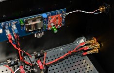
The input Gnd and Gnd for speaker out is connection on amp PCB as shown on picture. There is a short wire from PSU Gnd to PCB Gnd. I built the PSU so last C was close to amp PCB to have as short wires as possible. The rail fuses are also in the picture. With all the energy in the caps in supply I don't want to burn the PCB is something bad happens.
The PC and Focusrite is only connected via USB so Focusrite gets its power via USB. I have not tried to unplug the PC from its power supply to run on battery alone but I could try that next time.
I can make a measurement with input terminated (I understand this as grounded input?)
It seems the measurements makes some kind of sense...e.g. if I add extra mu-metal screen for interstage transformer I can see 50 Hz peak being reduced etc.
If a link exists with info of correct use of Focusrite / REW software for amp distortion/noise measurement I would like to read it.
I'd urge caution about 'interpreting' any changes in mains harmonic content on an REW plot between the various iterations with your mains feed and amp power supply. You don't seem to have achieved a rigorous measurement system that confirms your noise floor level, so you may still be chasing 'measurement ghosts' as a justification for amplifier changes.
One concern is due to your PC and focusrite powering, as you haven't identified what possible mains power noise loop could be in play with your DUT (eg. you could be using a laptop with your laptop and focusrite all floating - but I didn't see that clarified).
Another concern is if there is any difference between the signal input grounding point to your amp, and the speaker output grounding point, due to internal layout/wiring/circuit nodes.
That's not to say that the changes you are making may not be reasonable and interesting, but it makes any comparison of a single REW plot, or between plots, prone to just being subjective as you haven't yet presented results on your measurement setup noise floor.
One configuration for a noise floor test would be to terminate the signal input at the input socket but keeping the normal ground connection between incoming signal and amp ground. Same with the amp's output terminals, where you want the facusrite to connect to the output ground terminal, with a focusrite signal short at that point - the amp still has a resistive load on it, and can still accept an alternate floating signal generator input, as one form of this test should be to also get a benchmark when the amp is actually generating output signal power rather than just sitting at idle.
Attachments
Ok, my DIY measurement system is not a prof. system. It is Focusrite 2i2 and REW software on a laptop. Then a homemade box that converts from speaker banana plug in to RCA out and a pot so I can reduce the signal to the Focusrite input.
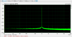
It seems everything I try on the PSU I can only provoke 100 Hz and hamonics and 50 Hz I can reduce by use of mu-metal screening. The 150/250 etc.....they just stay stable. I am about to belive that they occur inside the amp circuit and are not direct PSU related......but I might be wrong......
Which generation 2i2 do you have? I have had similar and they were not the device under test at all, but pickup of 50 Hz and harmonics through I think induction. Careful placememt of where the cables go, the device under test and also making sure you have no earth connection between the DUT and the focusrite are all key to not getting these sorts of artifacts.
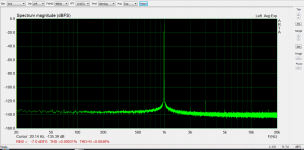
Below are loopback measurements I did earlier today on my Gen1 focusrite 2i2. The first is a balanced loopback. the second shows what happens (on the gen 1) if you use a TR cable for input of a SE source. Setup was output using a TRS cable to RCA with tip to hot and ring to ground of the RCA socket, then a cable with RCA to TR plug which is plugged back into the input.
I believe that at least with the Gen1 it is critical to make sure that the input is not shorted on either side of the balanced pair to avoid a massive drop in distortion performance. Note the presence of 50 150 and 250 hz spikes. This is just a loop back! The cable itself is picking it up.
I would use the same output and input cables you currently are and do a loopback with them and check that you are not getting the 50 hz and harmonics even when the DUT is out of the picture!
Tony.
Attachments
Absolutely Jan, but the other important thing with the focusrite (at least the gen 1) is that the distortion performance is also affected, not just the noise rejection performance.
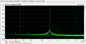
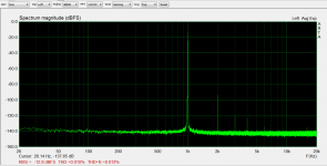
I was curious about my statement about it being more important to have the TRS plug on the input rather than the output, so I just did the mesurements again. Back to back, just swapping whether the TR end or the TRS end was plugged into either input or output. No chage in the distortion, both much worse than with the fully balanced cable, but with the TRS plug in the input the harmonics disapear.
First image is with the TRS on the output TR o the input, 2nd image is reversed. The 50Hz is worse now than earlier today, possibly because I have the laptop connected to the mains this time (it was on battery earlier).
edit: and since things had changed since earlier today I just did another balanced loopback which is the third image.
Tony.
Attachments

Last edited:
If a link exists with info of correct use of Focusrite / REW software for amp distortion/noise measurement I would like to read it.
Not specifically with REW but here were my comments a while back on the importance of cabling and ideally using a balanced to SE circuit on the output if outputting to an SE device, if you have a gen1 2i2. Got Focusrite Scarlett 2i2 (2nd gen) for measurements. What's next?
Hopefully that and the subsequent posts and discussion are helpful 🙂 I've been working on an unbalanced to balanced circuit this afternoon, whether it will prove to be better than using a balanced to SE on the output and simple RCA to TR cable on the input waits to be seen 🙂
Tony.
I have a gen1 2i2, and have the same experience.
But there is another possible issue. In the bal to se circuits you mostly see, all 4 resistors are the same. The problem (possibly) with that is that the input impedances seen by the two bal signals are unequal. Depending on the internal output resistors of the bal outputs, this can increase distortion.
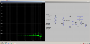
To keep the bal to se scaling correct, and the two input impedances the same, the resistor values connected to the inverting input should be 3x the values of the resistors connected to the non-inverting input. A quick LTspice test should confirm that, see attached. Currents in R3 & R12 are equal and voltages at opamp inputs are equal.
Jan
But there is another possible issue. In the bal to se circuits you mostly see, all 4 resistors are the same. The problem (possibly) with that is that the input impedances seen by the two bal signals are unequal. Depending on the internal output resistors of the bal outputs, this can increase distortion.
To keep the bal to se scaling correct, and the two input impedances the same, the resistor values connected to the inverting input should be 3x the values of the resistors connected to the non-inverting input. A quick LTspice test should confirm that, see attached. Currents in R3 & R12 are equal and voltages at opamp inputs are equal.
Jan
Attachments
Last edited:
Ok thanks Jan, I need to digest that 🙂 indeed i kept all of the resistances equal in my circuit. I shall see what happens in the sim. (though if it is like my unbalanced to balanced, the distortion in the sim may be so low as to not be detectable if there is a difference (spice vs real world problem 😉 )
Tony.
Tony.
See above for LTspice example. It may not be significant, depending on all the impedances involved.
(It has a gain of 1/2 but that's immaterial).
Jan
(It has a gain of 1/2 but that's immaterial).
Jan
Last edited:
Clearly I have a digestive problem (or I shouldn't have had that third glass of wine) 😀
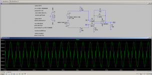
First plot shows the circuit as I did it, and the fft (which is obviously bogus, and not much use for real world figures).
Second shows what I thought you were saying (but clearly not) I was pretty sure the input resistors had to match for balanced, but if the inverting input is different then they can't. Anyway distortion reported as 24% with this 😀
edit: ah I see you have posted a circuit, I shall download and look 🙂
Tony.
Attachments
Last edited:
My Focusrite 2i2 is a 2nd Gen from 11/2017.
Until now I have only used the SE input (via a 6.3mm mono Jack to RCA converter). I can see the advantage to use balanced input if used properly. Also on output i use a 6.3mm mono Jack to RCA converter. I did a simple loop back test when I got the 2i2 to test the internal generator. It showed relative good performance and seemed good enough for "DIY use".
Until now I have only used the SE input (via a 6.3mm mono Jack to RCA converter). I can see the advantage to use balanced input if used properly. Also on output i use a 6.3mm mono Jack to RCA converter. I did a simple loop back test when I got the 2i2 to test the internal generator. It showed relative good performance and seemed good enough for "DIY use".
OK I think the second gen is not quite as sensitive to this issue as the first gen, but I have heard it is still somewhat affected.
Jan I didn't forget about your comments, but a couple of minutes after I saw it, I got some new plans from my other half (need to get up early and a bit of a full on day) so I still haven't had a chance to work out where I went wrong 😉
edit: OK I shouldn't use a * for multiply, just 3{res} but I can't see any difference in distortion either way 🙂
Tony.
Last edited:
- Home
- Amplifiers
- Power Supplies
- 150 Hz / 250 Hz / 350 Hz noise in linear PSU