Hi James, the two go mainly hand-in-hand, but I would say a smooth on axis, plus and minus 30 degrees maybe, frequency response is the priority.
Yes perhaps they could be tailored to a specific driver, this is still only a simulation though, I don't know how accurately it models the real world.
Yes perhaps they could be tailored to a specific driver, this is still only a simulation though, I don't know how accurately it models the real world.
Since this worked so well https://www.diyaudio.com/forums/full-range/361790-siegfried-linkwitz-miss-trick-20.html#post6402685 maybe try moving the driver to find the best exit angle, and/or increase the baffle thickness?
Hi Scott
I think I'd be quite happy with an approx. flat freq response at +/- 30* angle in front and from about 200Hz roll-off freq up to the treble area - the rear radiating angles/freq response isn't as significant for me as I use 1D diffusers behind the speakers but interested in the rear transient characteristics.
I had an interesting idea recently! What would happen if we added a circular version of the tapered slot as per the Karlson design, or a circular constriction, in front of the driver at the front of the torus curve.
I have a strange question - my Betsy OB drivers have a cone diameter just in 160mm and the surround is 10mm making the driver 180mm overall diameter (in front) - do I begin the inner diameter of the torus at 160, 170 or 180mm?
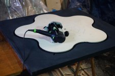
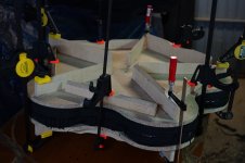
I will cut an 3mm thick metal plate to mount the driver between the front and back half torus'/tori - I thought initially to use a 15mm thick timber ply but the thinner plate should make it easier to assemble the 2 halves.
The 'hot knife' arrived today so can start cutting some styrene to see what problems arise ...
I think I'd be quite happy with an approx. flat freq response at +/- 30* angle in front and from about 200Hz roll-off freq up to the treble area - the rear radiating angles/freq response isn't as significant for me as I use 1D diffusers behind the speakers but interested in the rear transient characteristics.
I had an interesting idea recently! What would happen if we added a circular version of the tapered slot as per the Karlson design, or a circular constriction, in front of the driver at the front of the torus curve.
I have a strange question - my Betsy OB drivers have a cone diameter just in 160mm and the surround is 10mm making the driver 180mm overall diameter (in front) - do I begin the inner diameter of the torus at 160, 170 or 180mm?
I will cut an 3mm thick metal plate to mount the driver between the front and back half torus'/tori - I thought initially to use a 15mm thick timber ply but the thinner plate should make it easier to assemble the 2 halves.
The 'hot knife' arrived today so can start cutting some styrene to see what problems arise ...
^Scott
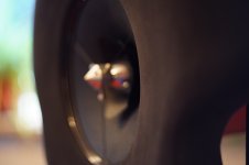
The diameter, thickness, exit flares and offset were all tuned to get that result. The torus center is a cylinder to allow me to adjust the driver offset. I think at this point reducing the ripple would require irregular perimeter and maybe even surface damping added.
The diameter, thickness, exit flares and offset were all tuned to get that result. The torus center is a cylinder to allow me to adjust the driver offset. I think at this point reducing the ripple would require irregular perimeter and maybe even surface damping added.
I'm really amazed at your ability to manipulate this program Don - many thanks - very instructive indeed.
Thanks.
When I was reading about Mattes baffles, I noticed that he used some quite dense rubber foam material and machined it to shape, (not moulded) an expensive process - I was wondering if this is to absorb driver vibrations/damping or effect higher freq radiating response (freq absorption) and if this could be included like the idea of absorbent material on the outside edge? Or if it would be at all significant?
Hard rubber would not absorb very much acoustically. It might dampen driver mechanical vibrations. I suppose this would help avoid vibrating the petals as the driver moves. I think the irregular perimeter is very interesting.
Some of the earlier models extended the low freq response and also have a pronounced dip around 2.5kHz would suit a number of accessible 8" FR drivers that have a cone resonance in that area - just saying …
It's all relative. It might be like trying to EQ out a null.
Last edited:
The simplest would be a square 😉 I did suggest that in one of the threads that spawned this one, no-one commented on it though..........
Did you mention something triangular, like a wankel rotor?
I like the idea of keeping some semblance or symmetry around the perimeter
Yeah, I like the appearance of symmetry. Maybe something elliptic, wankel or just not polar symmetric.
I think in most "normal" listening spaces, ie smallish and not overly reverberant, ideal dipole radiation isn't very important, the other attributes, lack of box and more ambience (any others?) will still be present.Hi Scott
I think I'd be quite happy with an approx. flat freq response at +/- 30* angle in front and from about 200Hz roll-off freq up to the treble area - the rear radiating angles/freq response isn't as significant for me as I use 1D diffusers behind the speakers but interested in the rear transient characteristics.
Sorry, I've no idea 🙂I had an interesting idea recently! What would happen if we added a circular version of the tapered slot as per the Karlson design, or a circular constriction, in front of the driver at the front of the torus curve.
I presume when you say surround you mean the suspension not the chassis. I would think ideally start the torus or waveguide at the outside edge of the surround.I have a strange question - my Betsy OB drivers have a cone diameter just in 160mm and the surround is 10mm making the driver 180mm overall diameter (in front) - do I begin the inner diameter of the torus at 160, 170 or 180mm?
Thanks, I thought you'd probably already done that 🙂 I think it's a good result and relatively simple to construct, having a conical waveguideThe diameter, thickness, exit flares and offset were all tuned to get that result.
Hi,
the EVA foam of my baffles is not the same as hard rubber, I think that the vibration absorbing properties of the material are better than hard rubber, but have no numbers on hand to proof it.
I´ve chosen the specific density of the EVA foam from several samples (and I have tried other materials before, including polystyrene, didn´t like it at all...), wanting
- some rigidity, to not have the petals flapping back and forth when Daniel Herskedal plays bass tuba
- low weight, in order to minimise all mass not being situated near mass centre, following Michael´s free-swinging approach
- a relatively soft surface after sanding, to minimise reflections from the material
- high inner damping, to suppress vibrations from the drivers as much as possible
As I don´t have equipment to measure surface or material vibration, I made several baffles, listened, and finally made the choice based on acoustic measurements, listening and feeling (the well-sanded EVA feels like a massive block of suede, quite a small tactile sensation...).
What I wanted to achieve was having a relatively small baffle providing a little bit better loading than a nude driver, but avoiding the negative effects of a baffle. A pretty good solution are certainly OllBolls wool/felt baffles, but I wanted something nicer... visually.
Of course an 8-inch fullrange driver in a small baffle will not represent a true dipole, but is maybe "close enough". I tried to "better" the rear radiation with an extra tweeter, but in the end returned to just the fullrange. Sounds better.
All the best
Mattes
Attachments
Isn't the answer because there is essentially no baffle so no baffle edge?If I use a driver, without baffle (nude), it doesn't have any on axis nulls either. You can easily confirm this with the Edge when the driver radiating surface and baffle edge are close together. If diffraction is a problem, why would it not be worst in this case with a circular, sharp edge?
If I use a driver, without baffle (nude), it doesn't have any on axis nulls either.
Isn't the answer because there is essentially no baffle so no baffle edge?
No. Of course there is an edge - it's at the OD of the driver's frame. It's a sharp, circular edge (meaning not rounded). Yet none of those terrible, horrible, no good diffraction ripples. Why not?
The answer is that the source is large compared to the dimension of the edge(s) where diffraction can take place (and does!). This smears out the diffraction in time and space just like Olson's example of a small driver on the surface of a sphere.
If you go back to my post (use the < icon in my quote above) you will see a measurement of a 15" nude driver that doesn't show diffraction. If you want to sim it in the edge it is actually very easy. Make sure the "Open Baffle" checkbox is checked. Choose a driver diameter and then set x and y baffle dims to be about 10% larger than that. Next, go to the input box "number of corners" and just add another digit, e.g. if it says "4" add a 1 at the end to make "41". Move the mouse over to the "Apply!" button below the baffle dims and click it. This will result in a circular baffle. Move the driver into the middle and click on several places off axis to see that the response is without ripples and just shows the directivity of the driver.
To see the opposite: a small driver centered in a circular baffle, just go up to the driver "Size" field and enter 25 (assuming you were simulating a much larger circular baffle). You will see very strong diffraction effects even though this is an open baffle dipole model.
Last edited:
The answer is that the source is large compared to the dimension of the edge(s) where diffraction can take place (and does!).
Which is what I meant by there being essentially no baffle edge, it's not seen by the source. Also a 15" driver will start beaming at a relatively low frequency.
Which is what I meant by there being essentially no baffle edge, it's not seen by the source. Also a 15" driver will start beaming at a relatively low frequency.
There is definitely an edge and its circular. I can't say for certain whether beaming is responsible for this but I don't think so. I have measured smaller drivers nude, for example 6" drivers, and there are still no diffraction ripples. Honestly, I haven't seen ripples with any driver I have measured nude. The 15 is just a great example IMO, so I tend to use it.
Last edited:
To see the opposite: a small driver centered in a circular baffle, just go up to the driver "Size" field and enter 25 (assuming you were simulating a much larger circular baffle). You will see very strong diffraction effects even though this is an open baffle dipole model.
Do you mean it shows the edge diffraction causing ripple?
Yes, of course, I understand that, perhaps it's a language issue when I say essentially it could have a different meaning for you. But compared to the source the baffle is small. There will still be some edge diffraction but it won't be easy to see the effect of it.There is definitely an edge and its circular.
Do you mean it shows the edge diffraction causing ripple?
Correct. When the driver radius is much smaller than the baffle radius it is essentially like a point source, and everywhere the edge is the same distance from it and so you get strong diffraction (I think this is the strongest of any shape).
Without changing the baffle radius, as you increase the driver radius the diffraction effects go away almost perfectly (there is still some residual ripple but it is around 1dB or less).
Likewise, you can reduce the baffle radius with a fixed driver radius and see the same thing.
The only difference is the frequency at which you see the dipole peak, which is determined by the baffle radius.
I'm glad to hear you say that because I couldn't quite get my head round what you said here 🙂
Regarding the diffraction of the edge being problematic, the diffraction is opposite in polarity from front and rear, and I would like to think that there is quite a lot of, if not complete, cancellation. This would be more true at low frequencies than higher ones I suppose. I also feel that the sonic influence of diffraction, just like jitter in digital music, is so over blown and concerns are so over-hyped that it is laughable. So maybe I am a little jaded about the whole thing.
Last edited:
I'd like to see results of a (nude) driver that operates at 1k to about 8k, not a 15". Not even a 6" driver...
And not a sim from the Edge...
And not a sim from the Edge...
Last edited:
- Home
- Loudspeakers
- Full Range
- Did Siegfried Linkwitz miss a trick?