>With such a transistor, 2SC3502 R14 will be superfluous.
Strangely, FFT looks much better with it.
Do we really need R3 (10 Ohm) ?
Strangely, FFT looks much better with it.
Do we really need R3 (10 Ohm) ?
Well and good.Need this resistor R3 . It is part of the correction of nested OOS,and also slightly increases the threshold for triggering the limiter
It remains to enter overload protection
It remains to enter overload protection
Last edited:
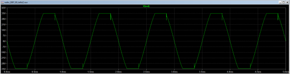
Looks better than before.
maybe, but the lighest overload and You will be kicked off the saddle, like when mounting a raged bull, try some 1.7V input and will see
To do this, a threshold limiter is introduced on the diodes.maybe, but the lighest overload and You will be kicked off the saddle, like when mounting a raged bull, try some 1.7V input and will see
maybe, but the lighest overload and You will be kicked off the saddle, like when mounting a raged bull, try some 1.7V input and will see
You mean this raged bull?
Attachments
Last edited:
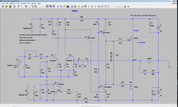
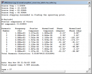
As I'm waiting for heatsinks for Wiederhold77 HexFet Quasi,
I simmed VHex 1 from Valery, recommended by Egra.
I don't know if I'm doing it wrong, but here are the results.
With these numbers, it looks like op-amp is really improving
things...
I tried different transistors, but no improvement was possible.
I simmed VHex 1 from Valery, recommended by Egra.
I don't know if I'm doing it wrong, but here are the results.
With these numbers, it looks like op-amp is really improving
things...
I tried different transistors, but no improvement was possible.
Attachments

Parallel to R14, put a capacitor with* 22nf-100nf, the clip will become normalYou mean this raged bull?
OPamp has a higher gain compared to discrete LTP. Deep GNFB.
Try inverse switching for discrete LTP.
Try inverse switching for discrete LTP.
Last edited:
You mean this raged bull?
🤣 Yes
Change the oramp model in LTS .
Parallel to R14, put a capacitor with* 22nf-100nf, the clip will become normal
It didn't help.
Also, subsequent simulations show not difference if done with or without R14. So, according to your previous advice, I removed R14.
The clip oscillations become better if I change the diodes to Schottky diodes (E.g. 1N5817), but it does affect Thd slightly...
So I guess that's not the way...
As for the model - in the sim I'm using LT1056 - built in into LT Spice.
In actual builds, I tend to use TL071.
I have a model for TL071, but if I use it - my .asc files will not work for you guys - op-amp models has to be imported into LTSpice directory tree, they are handled differently than transistor models from .lib files.
3rd party op-amp models are very awkward to use.
Perhaps I could use different op-amp model, that's built in into LTSpice standard library...
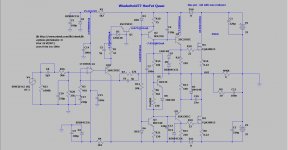
Some part values have been changed.Verify.The Microcap is excellent
Attachments
Last edited:

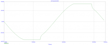
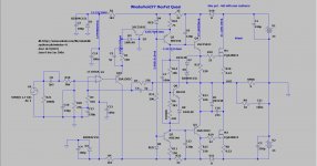
@Maxim. Since the missing parts are already on way from mouser, I would like to finalize the circuit of qhex version and I'm going to design the PCB. The amplifier shows ugly clipping characteristics when R1 = 33 Ohms are used. It looks much better with 100 Ohms (In original Wiederhold it is 1k). What do you think? Also, since I don’t have enough knowledge in LTSpice, could anyone simulate the Phase and Gain margin of the circuit? Currently I only have +/-33V Power Supply. This is why I set the simulation to 33V. Thank you for the help.
Attachments

Last edited:
capacitanc7 should be increased. 22PF
It is necessary to select it.
C12/c13 can also be increased
It is necessary to select it.
C12/c13 can also be increased
( It looks much better with 100 Ohms (In original Wiederhold it is 1k)]750ом УМЗЧ ВВ и СЛА
Last edited:
Egra, you are adding zener protection for the gate of M1, but not M2?
When I was selecting R1=33 Ohm, I did not test for clipping....
Depending on the Vpp of your audio source (I was assuming up to 1.2 V AC for my needs) - you may need to
increase R5 910 Ohm resistor to achieve lower gain - since you are using lower rail voltage.
910 Ohm was already aggressive 🙂 1k or 1k2 might be better.
Last edited:
Egra, you are adding zener protection for the gate of M1, but not M2?
When I was selecting R1=33 Ohm, I did not test for clipping....
Depending on the Vpp of your audio source (I was assuming up to 1.2 V AC for my needs) - you may need to
increase R5 910 Ohm resistor to achieve lower gain - since you are using lower rail voltage.
910 Ohm was already aggressive 🙂 1k or 1k2 might be better.
22 ohms in supply rails caused the clipping problem. So I left them, now everything seems right. I think it will be good already, I'm going to design the PCB. Minek, did you simulate Gain and Phase margin?
Attachments
You were referring to the circuitry in #259, weren't you? I'd not short R13, but bypass it with a 1N4001 Baxandall diode instead.What happens if you short out R13
Best regards!
- Home
- Amplifiers
- Solid State
- Unusual amp from 1987