Hello All.
I have some boards from Oliver..tda 1541 dac v2.3 .
I would like to use it in simultaneous mode as the I2Soverusb from JLsound is capable of.
Do you think i can connect directly to the DAC 1541 pins removing the attenuator.?
Or...is it better to use directly the last version RED Baron 5? In this case i need to prepare a new pcb as those pcbs are not available anymore.
What do you suggest to me?
maurizio
Last edited:
Yes you can...ony if you have the sim option on the board cause the layout is changing around the 5v .
Anyway let your ears decide for you....atenuation on Lre and Bck has poors and cons.
Anyway let your ears decide for you....atenuation on Lre and Bck has poors and cons.
HI...I'm sorry but what do you mean with SIM? Simultaneous mode?
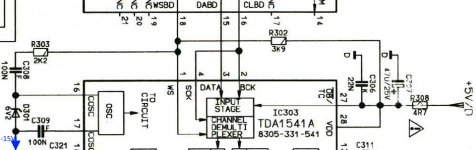
Here the schematic.
Reference TDA1541A DAC Modules - diyAudio
Then he developed the red baron..but it's not available anymore.
https://www.diyaudio.com/archive/bl...-red-baron-dac-module-v5-0-red-baron-v5.0.pdf
I see from the two schematics that he used two different circuits around the internal oscillator..Should i use the last one instead the use of the 74HC02?
What will happent if i will try to use the classic 47oPf capacitor between pin 16 and 17?
Many thanks in advance.
Maurizio
Yes, sim. is a shortcut for simultaneous, you can find it often written like this.
I just had a look to the V2.3 : it is an I2S mode board (data R is going to Bck), so no simultaneous mode on this board. Also the pin 27 must be shorted to pin 26 to switch the tda1541A in sim. mode (see datasheet : TDA1541A pdf, TDA1541A description, TDA1541A datasheets, TDA1541A view ::: ALLDATASHEET :::)
Thought : better a good layout for I2S than a hacked I2S board with too much long wires for sim. mode. If you have the choice between a sim mode layout from the beginning and an hasardous I2S attenuation (John gave it up at the end) : better the sim mode planned from the beginning on the board then.
If you hack aTDA1541 I2S made board for a simultaneous mode:
- you will need to lift the data R pin to connect it to the JLsound board. Each of the 4 wires/lines of the sim mode should be of the same length and the shorter possible, no more than 4 inch is advised, the shorter the better.
- easier to use coax 50 ohms cable because the gnd return will be easier and it will shield the lines in te same time with a hack where the wires can be working as antenna and catch bad things from outside or from the power supply traffos.
- you will need to check pins 26/27/25 where their connection is ruling one of the three operating mode of the the TDA1541 which one mode is the sim. mode you plan.
In te GB you can ask perhaps if one has a RedBaron to sold or a sota AYA board fro Audial. (the two are night and day imho)
hope that helps.
Last edited:
Hi .
Thanks for your tips.
Can you explain me how the different set of the internal oscillator on pin 16 and 17 can affect the sound?
Using the 470 Pf capacitor as in the tda1541 datasheet will degrade the sound?
Thanks in advance.
Maurizio
Thanks for your tips.
Can you explain me how the different set of the internal oscillator on pin 16 and 17 can affect the sound?
Using the 470 Pf capacitor as in the tda1541 datasheet will degrade the sound?
Thanks in advance.
Maurizio
It's in this long thread, I don't remember where. John has a shematic for that which is sighty different that te datasheet and I advice to follow his scheme.
But if you use a 470 pF as per datasheet, tou can not go wrong either: direct on the legs of the dip socket: mkp radial 5 mm cap Wima style or NPO or silver mica.
But if you use a 470 pF as per datasheet, tou can not go wrong either: direct on the legs of the dip socket: mkp radial 5 mm cap Wima style or NPO or silver mica.
Hi matthiasw,
The USB / Toslink / Coax DAPI receiver receiver we are now working on will replace the USB-only DAPI receiver if it performs equally well.
So we plan to use one universal DAPI receiver for future projects
So there will be two versions?
USB only DAPI receiver
AND
USB / Toslink / Coax DAPI receiver?
The USB / Toslink / Coax DAPI receiver receiver we are now working on will replace the USB-only DAPI receiver if it performs equally well.
So we plan to use one universal DAPI receiver for future projects
Hi diyiggy,
The DEM clock is generated by an on-chip oscillator. External 470pF capacitor sets the oscillator frequency:
Higher value capacitor -> lower DEM frequency
Lower value capacitor -> higher DEM frequency.
In order for Dynamic Element Matching to work, each clock period must have exactly equal duration. In other words it must have lowest possible jitter. Failing to do so will reduce resolution (DEM correction is not optimal).
The data sheet application works fine when no audio data is being streamed. But as soon music is being played, jitter on the DEM clock skyrockets and reduces usable resolution.
Solutions:
1) Increase oscillator bias. Connect one 6K8 resistor between pin 16 and 15 (-15V) and one 6K8 resistor between pin 17 and pin 15 (-15V). Increase capacitor value to 560 ... 680pF (check DEM frequency, it should be somewhere between 200KHz and 250 KHz. This mod makes the DEM oscillator far less sensitive to on-chip noise and fixes the DEM jitter issue. This is a quick, cheap and very effective fix.
2) Lower the DEM frequency to approx. 50Hz and increase the value of the decoupling caps. Timing cap value would be approx. 470nF and decoupling cap value to 100uF/25V (use caps with low DC leakage current). This will greatly reduce on-chip DEM switching noise energy (cleaner sound, darker background).
3) Use external DEM low jitter clock. Very difficult as the DEM oscillator is difficult to trigger reliably due to thermal drift (threshold levels change with chip temperature). Injecting external DEM clock also injects large amount of noise into the TDA1541A and that's also a big problem as this masks LSBs as well. (P)ECL logic may be used to inject a clock while injecting minimum noise. This also goes for I2S / SIM interfacing. (P)ECL can be configured in such way that it can drive the I2S interface inputs on the TDA1541A. This offers I2S attenuation and very low jitter (property of ECL, Emitter Coupled Logic).
The timing cap sets the DEM frequency and we want that frequency to remain as stable as possible. So we have to chose suitable caps like silvered mica, film or NPO. Use smallest possible capacitor, large capacitors and long wiring pick up unwanted noise. Use shortest possible wiring between both, chip and small DEM timing cap. SMD film / NPO caps are preferred.
It is possible to use injection locking to lock the DEM clock on a multiple of WS. If the DEM oscillator frequency is close enough to a multiple of WS (sample rate) it will automatically lock on to it (injection locking). This will also minimise DEM clock jitter but its tricky and lock can easily be lost by thermal drift. Trimmer could be used to fine trim the DEM frequency. Frequency meter is also recommended for checking the exact DEM frequency.
It's in this long thread, I don't remember where. John has a shematic for that which is sighty different that te datasheet and I advice to follow his scheme.
But if you use a 470 pF as per datasheet, tou can not go wrong either: direct on the legs of the dip socket: mkp radial 5 mm cap Wima style or NPO or silver mica.
The DEM clock is generated by an on-chip oscillator. External 470pF capacitor sets the oscillator frequency:
Higher value capacitor -> lower DEM frequency
Lower value capacitor -> higher DEM frequency.
In order for Dynamic Element Matching to work, each clock period must have exactly equal duration. In other words it must have lowest possible jitter. Failing to do so will reduce resolution (DEM correction is not optimal).
The data sheet application works fine when no audio data is being streamed. But as soon music is being played, jitter on the DEM clock skyrockets and reduces usable resolution.
Solutions:
1) Increase oscillator bias. Connect one 6K8 resistor between pin 16 and 15 (-15V) and one 6K8 resistor between pin 17 and pin 15 (-15V). Increase capacitor value to 560 ... 680pF (check DEM frequency, it should be somewhere between 200KHz and 250 KHz. This mod makes the DEM oscillator far less sensitive to on-chip noise and fixes the DEM jitter issue. This is a quick, cheap and very effective fix.
2) Lower the DEM frequency to approx. 50Hz and increase the value of the decoupling caps. Timing cap value would be approx. 470nF and decoupling cap value to 100uF/25V (use caps with low DC leakage current). This will greatly reduce on-chip DEM switching noise energy (cleaner sound, darker background).
3) Use external DEM low jitter clock. Very difficult as the DEM oscillator is difficult to trigger reliably due to thermal drift (threshold levels change with chip temperature). Injecting external DEM clock also injects large amount of noise into the TDA1541A and that's also a big problem as this masks LSBs as well. (P)ECL logic may be used to inject a clock while injecting minimum noise. This also goes for I2S / SIM interfacing. (P)ECL can be configured in such way that it can drive the I2S interface inputs on the TDA1541A. This offers I2S attenuation and very low jitter (property of ECL, Emitter Coupled Logic).
The timing cap sets the DEM frequency and we want that frequency to remain as stable as possible. So we have to chose suitable caps like silvered mica, film or NPO. Use smallest possible capacitor, large capacitors and long wiring pick up unwanted noise. Use shortest possible wiring between both, chip and small DEM timing cap. SMD film / NPO caps are preferred.
It is possible to use injection locking to lock the DEM clock on a multiple of WS. If the DEM oscillator frequency is close enough to a multiple of WS (sample rate) it will automatically lock on to it (injection locking). This will also minimise DEM clock jitter but its tricky and lock can easily be lost by thermal drift. Trimmer could be used to fine trim the DEM frequency. Frequency meter is also recommended for checking the exact DEM frequency.
Thank you John for all that details,
I had the ambition to get a scope to trim with a added pot air cap in // with the main pF DEM timing cap... but never had the courage. TDA1541-non-A never went as far than the late South-Asia factured TDA1541A and the earlier crowned. (both good though different sound)
I use your first 1) option everyday on my dac, thanks again for that, I confirm it's sounding good 🙂 - I use also the silver mica you advised in smd package-
The 2) with 470 nF/100 uF... I didn't try. 😱
The 3) : I followed the work you imputed and indeed I remember it seemed difficult cause the dividers on the masterclock path.
I don't use the Rogic solution tool from Bck or Lrck with a HC74xxx chip on pin 17 with a resistor and a cap (iirc) as well... I didn' t liked the emphasis on bass that can be sota with a proper local scheme decoupling with good fast linear darlington (emiter follower) low noise power supply....as some you showed iirc in this thread between the 1543 & the 1541 posts 😎 I find the 1) more elegant and working better in my set up... Nore the Rotel scheme that was said to be very good as well.
cheers, take care to your health you and brother and thanks again for all that nice sharing behavior.
Last edited:
I tried it with 44.1 kHz WS and 176.4 kHz DEM frequency, using a variable ceramic capacitor parallel to the DEM oscillator capacitor. However, whatever I tried, I was never able to achieve locking condition (not even at frequency set exactly to 176.4 kHz). I used a frequency meter and an oscilloscope to verify correct operation, but jitter was always present on DEM clock. What is the trick?It is possible to use injection locking to lock the DEM clock on a multiple of WS. If the DEM oscillator frequency is close enough to a multiple of WS (sample rate) it will automatically lock on to it (injection locking). This will also minimise DEM clock jitter but its tricky and lock can easily be lost by thermal drift. Trimmer could be used to fine trim the DEM frequency. Frequency meter is also recommended for checking the exact DEM frequency.
DEM clocking
Using currently also solution 1/ although I don't believe I increased the cap value... I'm looking also for the best way to drive the DEM clock externally... would this circuit from Henk ten Pierick be the best way to do it? Rbroer brought this up here:
https://www.diyaudio.com/forums/digital-line-level/11949-tda1541-dem-reclocking.html#post138362
1) Increase oscillator bias. Connect one 6K8 resistor between pin 16 and 15 (-15V) and one 6K8 resistor between pin 17 and pin 15 (-15V). Increase capacitor value to 560 ... 680pF (check DEM frequency, it should be somewhere between 200KHz and 250 KHz.
3) Use external DEM low jitter clock. (P)ECL logic may be used to inject a clock while injecting minimum noise.
Using currently also solution 1/ although I don't believe I increased the cap value... I'm looking also for the best way to drive the DEM clock externally... would this circuit from Henk ten Pierick be the best way to do it? Rbroer brought this up here:
https://www.diyaudio.com/forums/digital-line-level/11949-tda1541-dem-reclocking.html#post138362
Last edited:
What you could do Bernard is imho (at least I did that) to accept the intrinsic littles jitter here and there as the chip crosstalk and this one, but work with low frequencies as 5.xx/6.xx hz with fundamental SC-Cut crystals (see A Mori thread) to caress in fur direction 'woookie 😀 !' the Lrck...
All in simultaneous mode with not the IanCanada but the JLSounds board to make the digital front end distance short 'and acurate i2S front-end that is problematic with IanCanada I2StoPCM' At least the way TWTMC masterclock is made doesn't introduce a jitter due to the exta length of the uf-l wires. But the lessier the board the better.
Not sure at the end after some tests at house than fifo is more important than a good layout of the I2S or the simultaneous mode imho (fifo are not the brick wall for the moment they claim to be or I 'm hearing voices 😉)
Last edited:
I just want to hang in there ... I was about to try the Grundig mod, but I'm usually to lazy to setup a measurement....
From the Philips FT990 DSR (a Grundig Design, as can be clearly identified when one sees the layout)
@ John: have you tried that particular setup?
From the Philips FT990 DSR (a Grundig Design, as can be clearly identified when one sees the layout)
@ John: have you tried that particular setup?
Attachments
Last edited:
By the way - anyone knows whats up with the production run "HSH8844 2" - every single new old stock I've ordered, 2x way back in 2005 from Reichelt, 4x in 2018 from a forum member and now 2x from ELW-elektronik in Germany had this production code....
Or is it safe to say that Reichelt bought a some 10k chips back in the early 2000s and all these (If I remember correctly they were some €12 in 2006) spread out in the spare part/diy scene?
Or is it safe to say that Reichelt bought a some 10k chips back in the early 2000s and all these (If I remember correctly they were some €12 in 2006) spread out in the spare part/diy scene?
Hi weissi,
This mod works, but the DEM frequency (standard component values) should be somewhere between 200 KHz and 250 KHz.
In this schematic I assume that 4x oversampling is used. So WS signal frequency (that drives the DEM clock here) equals 44.1 * 4 = 176.4 KHz.
When using NOS, WS frequency will be 44.1 KHz and that's too low for standard (data sheet) active divider decoupling cap values.
The decoupling cap value is related to the DEM frequency, lower the DEM frequency requires higher value decoupling caps.
One option with NOS is dividing down the BCK signal. The division factor depends of the frame size. Frame size of 64 bits (I2S) is most often used.
For 64 bits / frame BCK frequency equals 2.8224 MHz @ 44.1 KHz sample rate.
The DEM divider therefore needs to divide by:
2822400 / 176400 = 16.
So this Grundig circuit can be used for NOS DACs by dividing BCK by 16.
It is best to use a synchronous -binary- counter like the 74HC161(74HCT161, 74LV161) for example.
pin 3, 4, 5, 6, 8 -> connect to GND
pin 1, 7, 9, 10, 16 -> connect to 5V
pin 2 -> connect to BCK
pin 11 -> connect to Grundig circuit.
Don't forget to place a 0.1uF ... 1uF decoupling cap between pin 8 and 16 (as close to the chip as possible).
When using SIM (Simultaneous, feeding L + R data into the TDA1541A simultaneously) interface, BCK rate may differ, that's no problem as we can choose between following options with the 74HC161 divider:
pin 11 -> divide by 16
pin 12 -> divide by 8
pin 13 -> divide by 4
pin 14 -> divide by 2
So all you need to know is the exact BCK frequency for SIM and choose correct division factor (output pin of the 74HC161) to get 176.4 KHz DEM frequency.
Other option is to use 44.1 KHz WS frequency and increase decoupling cap value to 2 ... 2.2uF.
One could stack 2 x 1uF/16V SMD 1210 SMD film cap from Panasonic / Cornell Dubilier or use (WIMA) 2.2uF film caps.
@ John: have you tried that particular setup?
This mod works, but the DEM frequency (standard component values) should be somewhere between 200 KHz and 250 KHz.
In this schematic I assume that 4x oversampling is used. So WS signal frequency (that drives the DEM clock here) equals 44.1 * 4 = 176.4 KHz.
When using NOS, WS frequency will be 44.1 KHz and that's too low for standard (data sheet) active divider decoupling cap values.
The decoupling cap value is related to the DEM frequency, lower the DEM frequency requires higher value decoupling caps.
One option with NOS is dividing down the BCK signal. The division factor depends of the frame size. Frame size of 64 bits (I2S) is most often used.
For 64 bits / frame BCK frequency equals 2.8224 MHz @ 44.1 KHz sample rate.
The DEM divider therefore needs to divide by:
2822400 / 176400 = 16.
So this Grundig circuit can be used for NOS DACs by dividing BCK by 16.
It is best to use a synchronous -binary- counter like the 74HC161(74HCT161, 74LV161) for example.
pin 3, 4, 5, 6, 8 -> connect to GND
pin 1, 7, 9, 10, 16 -> connect to 5V
pin 2 -> connect to BCK
pin 11 -> connect to Grundig circuit.
Don't forget to place a 0.1uF ... 1uF decoupling cap between pin 8 and 16 (as close to the chip as possible).
When using SIM (Simultaneous, feeding L + R data into the TDA1541A simultaneously) interface, BCK rate may differ, that's no problem as we can choose between following options with the 74HC161 divider:
pin 11 -> divide by 16
pin 12 -> divide by 8
pin 13 -> divide by 4
pin 14 -> divide by 2
So all you need to know is the exact BCK frequency for SIM and choose correct division factor (output pin of the 74HC161) to get 176.4 KHz DEM frequency.
Other option is to use 44.1 KHz WS frequency and increase decoupling cap value to 2 ... 2.2uF.
One could stack 2 x 1uF/16V SMD 1210 SMD film cap from Panasonic / Cornell Dubilier or use (WIMA) 2.2uF film caps.
Hi Berny,
I tried the circuit from Henk ten Pierick, it sometimes works and sometimes doesn't. It's a critical circuit and transistor properties (HFE, Vbe) have impact on stability. I also got spurious oscillations from both 1.2nF caps so I increased the value to 100nF (Grundig mod also uses 100nF).
Even when it locks, there is still considerable jitter on the DEM clock and it can lock out again as chip temperature (and related Vbe) changes. It helps to thermally couple both, transistors and TDA1541A and use a dual transistor with good matching.
Best results (lowest jitter / noise) clock injection was obtained using ECL (Emitter Coupled Logic). It serves two purposes, a very low jitter divider (using ECL flip/flop or ECL divider) and it offers differential output to drive the DEM oscillator.
The trick is DC level shifting in order to obtain stable triggering of the DEM oscillator. I used a split emitter resistor (ECL requires external load resistors). The resistor connected to the ECL output needs to be bypassed by a capacitor to maintain full signal amplitude while DC level is changed to the desired value.
DEM clock injection is always a balancing act between locking, jitter and noise injection. Remember we are trying to stop oscillation and then inject a signal into an oscillator circuit that is designed to oscillate.
The trick is DC level shifting in order to obtain stable triggering of the DEM oscillator. I used a split emitter resistor (ECL requires external load resistors). The resistor connected to the ECL output needs to be bypassed by a capacitor to maintain full signal amplitude while DC level is changed to the desired value.
Oops, came to the conclusion that I was using the 470pF with the pull down resistors... so not completely into the thought range. Is there a simple way to measure the DEM frequency as probe or multmeter will add about 100pF to the setup and influence the frequency...
I have also been looking for an ecl devider at Mouser... but it seems to stop at factor 4 or 8... and need 64 to convert BCK to DEM for my NOS version
John, was there a version of your TDA1541 dac using an ECL driver that was published? Have been looking several hours, but the thread became so long.. couldn't find anything.
Thanks for the help!
Yes just add 100 pf smd silver mica to your next Mousser or Farnell purchase, direct on the dip pins.
Hi ecdesigns,
I must say the only one specification of the PowerDAC I am a little bit worried about is the high output impedance of 1.7 Ohms.
Certainly it is perfect for a headphone amp but for a power amp output would a much lower impedance be desirable.
What I can imagine is that it will sound ultra transparent and clean but maybe offer less slam and drive.
Please, can you comment on this point.
Thank you
Matt
Last edited:
- Home
- Source & Line
- Digital Line Level
- Building the ultimate NOS DAC using TDA1541A