Even plain Elektro-optik link to normal DACs is better than anything I have tried so far:
AMNESIS VFET plus Elektro-optik link. - YouTube
Cheers,
M.
AMNESIS VFET plus Elektro-optik link. - YouTube
Cheers,
M.
Hi andrea,
Jitter could be compared to a virus, once it has spread, it is no longer containable, regardless of the methods used, game over.
When attempting to block jitter in a DAC, the jitter has already spread all over the place .... game over.
This is an unprecise sweeping statement that is simply not true.
//
Makes me think that people having academic knowledge and distributes bad or good notes but not too much in the diy should come not only with critic notes like a professor but also contribute "academicly".
TNT, may you mind to write a sticky about jitter, filters, oversamplings, speed of circuits and clock and how they impacts the sound of the dac to be able to hear the difference with ears and to know the culprits by listening ?
Should be usefull both for PCM and DS dac chips, NOS and no-NOS .
I think such good professor people like you are able to write such sticky, I am not. Maybe we focus too much on some things/concepts without be able for most of us , modest enthusiasts, not to make the difference at ears ?
This Digital Line section disearves such a sticky imho ?
Hi andrea,
Jitter could be compared to a virus, once it has spread, it is no longer containable, regardless of the methods used, game over.
When attempting to block jitter in a DAC, the jitter has already spread all over the place .... game over.
From a theoretical perspective this isn't true. A "virused" jitter signal can be brought back to a digital file as absent of jitter. It can then be reintroduced later in time into another DAC network with some "new" form of jitter introduced. in other words it can be eliminated by returning it back to a digital file. Hence if a digital signal can be brought back to the equivalent of a digital file it can never be game over.
Although it can be argued that the jitter can remain in the system in forever time (as decaying by some form) the level of such jitter at some point can be considered irrelevant, and whereupon other artifacts can take over as the more dominant noise source (anything not signal). This is not to suggest that jitter can't be a major contributor to the quality of reproduction.
Exactly what I said in my previous posts, if the jitter in the DAC is source dependent it does mean that there is something wrong in the interposed devices that don't do correctly the job (remove the jitter coming from the source).
Here you can find some measurements of a FIFO buffer device
The Well Tempered Master Clock - Building a low phase noise/jitter crystal oscillator
The jitter is only partially removed so a part of the jitter coming from the source is reflected to the output affecting the timing of the DAC.
Not even a very good master clock helps to remove totally the jitter of the source, so the DAC is source dependent.
But this does not mean that the jitter could not be totally removed, I have already explained the ritght way to do the job in post #7686
Building the ultimate NOS DAC using TDA1541A
Hi matthiasw,
I tried that before, many times, absolutely convinced that direct I2S interface is the best way to go. I tried every practical isolator and every practical way of combining master clocks & FIFO re-clocker.
The end result of these exhaustive tests is the ElectroTos interface and the ElectroTos low jitter protocol.
I will list its advantages again:
- Perfect galvanic insulation (LED -> Toslink optical receiver, very low coupling capacitance).
- Low jitter (coaxial interlink, unique low jitter protocol).
- Extra jitter reduction inside the DAC with modified PLL.
- Fewest practical signal changes to transmit a given amount of data (minimum data bandwidth required, lowest switching noise energy).
- Band-limited output (20MHz, greatly reduced noise injection, greatly reduced issues with parasitics inside the DAC circuits).
- Jitter / noise is tackled -before- the signal is routed to the DAC, this way it can't spread.
There is a lively discussion about ECDESIGNS products on AS forum:
ECdesigns - Page 39 - DAC - Digital to Analog Conversion - Audiophile Style
Thank you
Matt
Hi I took aa quick look at the pages from the link.
.
It is about optical isolation.
I think that it is possible to achieve good isolation of audio digital interface.
- First isolate visual unit (dysplay, TV etc) using typically HDMI cable. With optical HDMI like this one. Amazon.com: FIBBR Crystal Fiber Optic HDMI Cable High Speed 18Gbps- 4K 60hz Hdmi Cable HDCP 2.2, HDR 10 and Dolby Vision, 4:4:4, HDMI 2.0 Cable for UHD TV, Blue-ray Player, PC, Xbox, PS4 PS4Pro, Projector, 3.3ft: Industrial & Scientific
or this
Amazon.com: HDMI Fiber Optic Cable HDMI 2.0 18Gbps Active Optical Cable (AOC) / UHD 4K 60FPS 4:4:4 (5ft (1.5m)): Electronics
Maybe better because it is clear from the picture that metal cans of the 2 connectors are NOT conneted. So the groundings from HDMI is not connected to groundings metal can at the USB.
.
Next Adopt digital bus from the usb interface to optical driver and output. There are some Thunderbolt cables with differential driver-to-fibreoptics and opposite.
Thunderbolt™ Optical Cables | Corning
I think that it is possible to transfer 4 lines digital bus with this type of connection without making special cables?
.
it is only a need to design digtal circuit from single ended signal's to differential standard?
.
Or use some fibre optics conns (Google: Avago) and cables for every digital audio line like MSB did.
.
Tip for very good USB standard cable Phoenix contact. (They using firewire cable...)
Security Check
.
cheers
.
It is about optical isolation.
I think that it is possible to achieve good isolation of audio digital interface.
- First isolate visual unit (dysplay, TV etc) using typically HDMI cable. With optical HDMI like this one. Amazon.com: FIBBR Crystal Fiber Optic HDMI Cable High Speed 18Gbps- 4K 60hz Hdmi Cable HDCP 2.2, HDR 10 and Dolby Vision, 4:4:4, HDMI 2.0 Cable for UHD TV, Blue-ray Player, PC, Xbox, PS4 PS4Pro, Projector, 3.3ft: Industrial & Scientific
or this
Amazon.com: HDMI Fiber Optic Cable HDMI 2.0 18Gbps Active Optical Cable (AOC) / UHD 4K 60FPS 4:4:4 (5ft (1.5m)): Electronics
Maybe better because it is clear from the picture that metal cans of the 2 connectors are NOT conneted. So the groundings from HDMI is not connected to groundings metal can at the USB.
.
Next Adopt digital bus from the usb interface to optical driver and output. There are some Thunderbolt cables with differential driver-to-fibreoptics and opposite.
Thunderbolt™ Optical Cables | Corning
I think that it is possible to transfer 4 lines digital bus with this type of connection without making special cables?
.
it is only a need to design digtal circuit from single ended signal's to differential standard?
.
Or use some fibre optics conns (Google: Avago) and cables for every digital audio line like MSB did.
.
Tip for very good USB standard cable Phoenix contact. (They using firewire cable...)
Security Check
.
cheers
Hello, after a long time with he Mosaic UV i'd like to ask how do they compare to the current offerings (UPL96ETL , U96ETL). It seems there have been important changes in the gear, buy I would very much like to know how these translate to SQ comparisons between both.
When comparing very good amplifiers with a system that offers almost zero distortion there is a day and night improvement. Sound turns in to highly realistic music. So this amplifier distortion however small we think it is, prevents us from reproducing realistic music. This is a pity after going to extremes to get the source right.
I may have posted this before but please read this article:
The serious flaws of voltage drive | Current-Drive - The Natural Way of Loudspeaker Operation
So one would think, ok use constant current steering and all will be fine, unfortunately this is not the case. Think of speaker resonance where the speaker impedance peaks, this is only one of the problems with constant current steering. Most speakers are also more or less optimised for constant voltage steering, so constant current steering won't work well with these speakers.
What do we actually want? We want the speaker membrane to accurately track the amplifier input voltage, even when external forces (pressure) are working against or in favour of the membrane movement.
So I figured, why not ditch the classical open loop audio amplifier concept and replace it with a servo system. Philips made some attempts decades ago with the motional feedback system (MFB) for bass only.
Ecdesigns,
I just read this post from a while back. I have played with "current drive" and the taming of impedance peaks with mechanical methods (flow resistance) on the drivers. I did not continue the investigations due to external reasons, I think it could be made to work very well and there can be multi driver/way systems. Have you tried this with your speakers? (ThorstenL wrote ages ago about this and it grabbed my attention since then).
S
Hi matthiasw,
The Fractal PowerDAC has NO conventional analogue signal path with RCA interlinks and (pre) amps. There is no built-in digital nor analogue amplifier or analogue buffer of any kind.
PowerDAC signal path:
Balanced stabilised power supply -> 32 digital power switches (18V / 4.5A / 0.02R Rdson) -> 40 power resistors (10W 0.01% thin film resistor clusters mounted on a big heat sink) -> speaker.
My aim was not attempting to improve the analogue signal path (interlinks, (pre) amps) but simply throwing it out completely. This will also eliminate all related problems, distortion and degrading.
To answer your question, the PowerDAC provides most realistic music reproduction as it no longer suffers from analogue circuit degrading.
The Fractal PowerDAC is basically a high power version of the existing DA96ETF:
DA96 ETF: 3V6pp output, 375 Ohm output impedance, 2 milli watts rms in 250 Ohms.
Fractal PowerDAC: 3V6pp ... 18 Vpp, 1.7 Ohm output impedance (golden ratio matching with my open baffle speakers) and up to 6W rms output.
The speaker is connected to the Fractal power resistor array. There are no active buffers or amplifiers, nothing, just digital on/off switches and power resistors to generate a pure analogue output signal for the speaker.
This is no class D or DSD!
Efficiency is low (15% max.) so it is primarily intended for driving efficient speakers (90dB and up) and it is ideal for driving headphones
The PowerDAC consumes up to 120 watts continuous (at max. volume setting), so it has a huge heat sink and it doesn't even look remotely like the DA96ETF.
The prototype has a built in (insulated) U192ETL (the improved modified version). So it's basically a complete audio set in one box, Mains power in, USB in, speakers out.
Because I use the original DA96ETF logic board it is still possible to connect the PowerDAC to an external UPL96ETL.
Lossless volume control is obtained by programming the supply voltage and with stepped power shunts (parallel with the speaker). Volume can be controlled with an IR remote control.
The list of factors that can still degrade music reproduction quality is roughly narrowed down to:
- Recording quality.
- Source (has to offer verified bit-perfect playback and reasonably low interference).
- Speakers.
Hi ecdesigns,
any updates about the PowerDAC?
Thank you
Matt
Power DAC is a great concept
While the proof will be in the pudding, the PowerDAC concept is compelling.
Once we get a traditional DAC to its peak performance (clock, power, I/V output buffer) every optimization of the sound of a system tends to be eliminating subtractive elements of the electronics. IE removing signal degradation due to coupling caps, resistors, signal transformers etc. Having seen the improvements just by replacing or eliminating these elements it is hard to imagine how good a system could be if all of this was simply eliminated.
I guess the rest would be to pair it with speakers that work well with it in the room.
Agree,
I have two-way JBLs with 99dB sensitivity which should be a good match for the PowerDAC.
Matt
I have two-way JBLs with 99dB sensitivity which should be a good match for the PowerDAC.
Matt
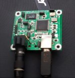
Another option for those intrigued about Elektro-optik link.
Use an USB-to-SPDIF/Toslink converter, like the one in the picture (inexpensive and good), remove the Toslink Transmitter and wire the Toslink output to the SPDIF connector. In this particular module, which I am very fond of, the coaxial output is transformer coupled so I removed the Tx and made sure that the ground of the connector was properly grounded.
Edit to be more clear:
1) Remove the Optical Transmitter.
2) Remove the SPDIF coupling transformer.
3) Connect "optical signal" to "coaxial signal" and "ground to coaxial ground".
Of course you still have to install the Red LED/Toslink adaptor to one end of the signal cable to be connected to your DAC's optical input. This is to have totally clean and high Q sound from a PC source. 😎
Of course, your software will then be the limiting step to great sound...
I hope you like it,
M.
PS: of course, you can also keep the Toslink Transmitter and wire the Coaxial connector in parallel, to be able to compare between cable formats...😉
Attachments
Last edited:
Hi,
This is one example:
Hi-Fi CM6631A 192KHZ to Coaxial Optical SPDIF Convertor DAC Board 24bit USB 2.0 | eBay
Greetings,
M.
This is one example:
Hi-Fi CM6631A 192KHZ to Coaxial Optical SPDIF Convertor DAC Board 24bit USB 2.0 | eBay
Greetings,
M.
It sounds absolutely clean and fantastic.
Now I wonder if I may mod the MOSAIC UV to handle Optic input...probably not...🙁
Now I wonder if I may mod the MOSAIC UV to handle Optic input...probably not...🙁
Hi matthiasw,
I have been optimising the Fractal D/A converter driver boards. PCBs for the next test version have been ordered.
There are plans to offer a bridge version (double output power) for driving less sensitive speakers.
Focus right now is on the development of a novel DAPI (Digital Audio Parallel Interface) receiver for the PowerDAC and headphones PowerDAC.
USB only DAPI receiver, proof of concept version, is already up and running. The USB / Toslink / Coax DAPI receiver is under development.
any updates about the PowerDAC?
I have been optimising the Fractal D/A converter driver boards. PCBs for the next test version have been ordered.
There are plans to offer a bridge version (double output power) for driving less sensitive speakers.
Focus right now is on the development of a novel DAPI (Digital Audio Parallel Interface) receiver for the PowerDAC and headphones PowerDAC.
USB only DAPI receiver, proof of concept version, is already up and running. The USB / Toslink / Coax DAPI receiver is under development.
- Home
- Source & Line
- Digital Line Level
- Building the ultimate NOS DAC using TDA1541A