@MEPER, mine is in one chassis (stereo), one PSU.
I don't know why it decreases in 13K-20K region - no filtering that I would know of.
And I do not hear anything with the ear to the tweeter, I only hear the mains hum from the woofers. But what is interesting, I hear more mains hum from the left channel, the right channel is less noisy to the ear, I am absolutely sure about this. Strange.
Strange but the R-channel looks nicer apart from the higher noise floor.
My 94 dB speakers are "hum-free" with ears as close to the woofer that is possible. Also tweeter is very silent.
So both your L and R channel was measured in same conditions. The 2i2 (or what you use) and internal sine generator was set to same values?
Can you repeat the measurement results?
My 94 dB speakers are "hum-free" with ears as close to the woofer that is possible. Also tweeter is very silent.
So both your L and R channel was measured in same conditions. The 2i2 (or what you use) and internal sine generator was set to same values?
Can you repeat the measurement results?
Have you checked bias on both channels?
Also maybe perform a loop-back test on 2i2 to check that setup is perfect. Then noise floor should be at -140 dB or so......and very low distortion.
Also maybe perform a loop-back test on 2i2 to check that setup is perfect. Then noise floor should be at -140 dB or so......and very low distortion.
Yes, L and R channels were measured in the same conditions and the same 2i2 and REW settings, just reconnecting the cables to the input and output of the amp.
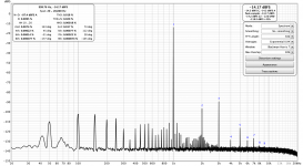
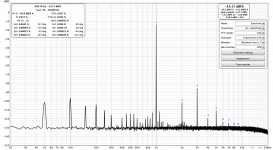
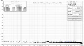
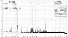
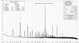
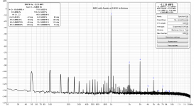
I cannot redo the measurements today, but I also have another measurements from the same session, but with the lower signal level - generator signal directly from the 2i2 output to the amp input, without the pre-amp. This gives 1.92V on the output of the amp, instead of 2.83V as in the measuments above. You can see in the pictures attached that on the lower signal the floor on the R channel is much lower, but still a bit higher than on the L channel (-130dBFS vs -138dBFS), and then you can see all the same hum as on the L channel. When the signal is increased, it makes the noise floor higher and it hides the lower mains hum peaks.
The loopback of 2i2 with pre-amp is fine, please see the last picture.
My only suspect after visual inspection of my amp is the soldering of one of the R channel output posts. It does not look perfect so perhaps a cold joint could introduce more noise on the higher signal levels? I will try to reflow it tomorrow and then make measurements again.
I do not know how to measure bias in M2X, I suppose it's automatic. But I did make DC adjustments on the output with shortend inputs, and it gets to just a few mV when the amp is up to the normal working temperature.
Attachments
Bias can be measured by measure the voltage drop over one of the source resistors in output stage. It is almost identical with rail current.
The loop back test looks fine and the drop in noise above 13 kHz is something in test system.
The loop back test looks fine and the drop in noise above 13 kHz is something in test system.
Do you feed the 2i2 with 2.83 V or do you have a divider network from the 8R resistor?
I use a 1/10 divider from my 6R8 resistor to be sure not to overload the input of 2i2 also so I can measure THD when amp deliver some watts.
I use a 1/10 divider from my 6R8 resistor to be sure not to overload the input of 2i2 also so I can measure THD when amp deliver some watts.
I feed 2.83V directly to 2i2. It's input can handle up to 22 dBu (9.75V) on minimum gain, so it's perfectly fine for 2i2 and I do not use the divider network. Another thing is that I am still waiting for the 8ohm 100W resistors to arrive, so I measured with the real speakers (Overnigh Sensation) attached, therefore the signal is not exactly 1W anyway. But that doesn't matter for the difference between the channels (I used the same loudspeaker in both cases).
Concerning the bias current, if I understood correctly, I measured the votage drop on all of the 0R47 resistors (R13 and R14). It was 0.62 V after the power up and changed very little (0.610-0.618 V) after half an hour. So the bias current should be about 1.30-1.32A - the same on both channels.
Concerning the bias current, if I understood correctly, I measured the votage drop on all of the 0R47 resistors (R13 and R14). It was 0.62 V after the power up and changed very little (0.610-0.618 V) after half an hour. So the bias current should be about 1.30-1.32A - the same on both channels.
Ok, the speaker is a more complex load so maybe reason for the many spikes. Your bias is fine.
I could probably get a bit lower noise floor without the divider and then reduce gain for 2i2 input. I usually have monitor turned up to max. as far as I remember.
But this does not explain the difference between your L and R channels.
I could probably get a bit lower noise floor without the divider and then reduce gain for 2i2 input. I usually have monitor turned up to max. as far as I remember.
But this does not explain the difference between your L and R channels.
Patrick / ItsAllInMyHead,
If I were you I would set my power supply for 46 volts and, if it has current limiting, set the current limit pretty low, like 40mA. Apply the positive lead to Pin3 (including the milliammeter) and the negative lead to Pin1. Read the current. I would leave the other pins open and floating.
Why 46 volts? Because the middle of the acceptable supply range for M2 and M2x, is +23V and -23V. Thus 46 volts end to end.
What should the milliammeter say for Norwood at 46 volts total? Somewhere between 8mA and 30mA. If you want to double check these numbers, the mfr datasheets for the two ICs each give a Supply Current specification (range), and you can calculate the current drawn by the bias resistors R1 and R2 using ordinary algebra.
Everything seems clear. However, I want to make sure that I can check all daughter cards exactly this way (46V - pin3, negative - pin1)
@darr
maybe I am missing the context here but I have not measured the current draw of the DBs and I don't see a reason why it should exceed the opamp specs. It should actually be very constant for all Norwood boards out there given they all see the 600ohms EDCOR as the load. This is provided the voltage supplied is the same of course and that the rest of the board is identical and unmodified and not malfunctioning.
I am always careful with that and knowing not to exceed the supply the rated voltage of the opamp is more important. Some DBs use 12V zeners others use 10V ones.
Clearly there are possible assembly errors which cannot be detected with only a variable power supply and an ammeter. If the circuit is oscillating, and if in the test fixture it drives no load at all, I doubt you could detect that without an oscilloscope (for example). I doubt that an ammeter would show anything unusual.
So you need to decide what types of flaws you wish to detect, before designing your test procedure. If I remember correctly, member pfarrell was worried about one certain type of flaw / error / builder's mistake, and sought a simple way to catch that one mistake. His modest goal was to increase the odds that he could find and discard "bad" daughter cards, so they have no opportunity to make the entire M2x amplifier catch fire and explode.
So you need to decide what types of flaws you wish to detect, before designing your test procedure. If I remember correctly, member pfarrell was worried about one certain type of flaw / error / builder's mistake, and sought a simple way to catch that one mistake. His modest goal was to increase the odds that he could find and discard "bad" daughter cards, so they have no opportunity to make the entire M2x amplifier catch fire and explode.
Yes, I mean exactly the assembly control. The current data for each of the DB are given, but I want to be sure that each of them is powered equally + 46V on pins 3 and 1
Hi all. I had time to tinker with REW and M2X again. And I found the culprit of the higher noise floor and additional harmonics on one of the channels! This happens to be one of my most beloved Tucson cards 🙁 This is, probably, quite subtle in reality. I do not hear any problems when listening to it - but you can definitely see it in the graphs, and it's there for real - I made measurements with all the cards I have (I do not have Ishikawa built). All of them measured well and very similar, except of this one "faulty" Tucson.
Please see the measurement graphs below. Again, please disregard the mains hum - this has to be dealt with yet. But looking at harmonics, I can say that preferring one of the buffer cards over the others is very much psycologic and subjective - I cannot see any significant differences in harmonics signature of the amp between them (well, maybe there are other differences that are not shown on FFT analysis).
The graphs also confirm one thing that I can actually hear - my Mountain View is a bit more sensitive to the mains hum that other cards.
Over all, a very interesting experience with REW measurements.
But it made me sad about my Tucson - for all the unexplainable subjective reasons I like them most (perhaps of the "fault" of one of them?). What could make one Tucson increase the noise floor by about 25dBFS and add even order harmonics (mainly 4th and 6th). It uses SMD OPA1611 chip. With so small number of the parts on the board, is the chip the main suspect? I soldered it using hot air, contacts look clean and nice, chance of overheating while soldering is minimal, I think. Could it be the faulty chip itself?
-Alvis
Attachments


If you want to screen some just-built M2x daughter cards, and if you know in advance they are ONLY going to be used inside one specific amplifier (yours!) with one specific power supply, then you only have two numbers to think about
Condition #2 occurs at power up, as the optoisolator-controlled bias circuit slooooooooowly ramps up the current in the MOSFET output stages.
Imagine there's a rotary knob with a pointer. At zero degrees, the pointer indicates V(1) above. At 270 degrees, the pointer indicates V(2) above.
Now just turn the dial to a setting that YOU think is reasonable. All done!
Naturally the situation becomes more complicated when you know in advance that these daughter cards are going to be installed inside more than one M2x, and see more than one power supply. Now you've got several max_V values and several min_V values: one from each amp+PSU. You need to somehow combine them together into a single setting. You might choose the biggest voltage among them. You might choose the smallest voltage among them. You might choose to calculate the average value of all the voltages. As long as you carefully think about WHY you're calculating this number, I expect that any voltage you select is probably going to be just fine.
1. Your power supply's minimum (Vtoprail - Vbottomrail) voltage: when the PSU is supplying the full, 100% class-A output current
2. Your power supply's maximum (Vtoprail - Vbottomrail) voltage: when the PSU is on but the amplifier hasn't yet begun to draw any class-A output current
2. Your power supply's maximum (Vtoprail - Vbottomrail) voltage: when the PSU is on but the amplifier hasn't yet begun to draw any class-A output current
Condition #2 occurs at power up, as the optoisolator-controlled bias circuit slooooooooowly ramps up the current in the MOSFET output stages.
Imagine there's a rotary knob with a pointer. At zero degrees, the pointer indicates V(1) above. At 270 degrees, the pointer indicates V(2) above.
Now just turn the dial to a setting that YOU think is reasonable. All done!
Naturally the situation becomes more complicated when you know in advance that these daughter cards are going to be installed inside more than one M2x, and see more than one power supply. Now you've got several max_V values and several min_V values: one from each amp+PSU. You need to somehow combine them together into a single setting. You might choose the biggest voltage among them. You might choose the smallest voltage among them. You might choose to calculate the average value of all the voltages. As long as you carefully think about WHY you're calculating this number, I expect that any voltage you select is probably going to be just fine.
Hi all. I had time to tinker with REW and M2X again. And I found the culprit...
-Alvis
That's great that you found the issue. TUCSON is the simplest card so it shouldn't be hard to figure out the bad component. I use the old school opa604 on tha.
Worst case it's the opamp.
I just got the missing diodes and the contact pins for the IPS7 so I should be able to compare side by side. I am interested in the seeing if the higher PSRR of the IPS7 makes a difference. Still waiting for some equipment to implement your testing scheme.
Listening report on IPS7 board with LMA49720 dual opamp vs TUCSON with OPA604.
I can't tell if the high frequency is a little rolled off and sweeter or if the LMA49720 distortion is lower, in any case the new combination brings out the midrange detail and expanded soundstage. I heard parts of the program I couldn't hear in the TUCSON.
I would describe the TUCSON as a dynamic wall of sound, the IPS7 with LMA49720 is an imaging and clarity machine. Additionally, the IPS7 seems to vanquish any form of hum/noise.
I have no idea which one I prefer, each one excels with certain music types.
I need to test the OPA134+IPS7 but I highly recommend building this card and experience it for yourself.
I would like to thank Mark for producing the board and making the PCB available for free!
grataku, congratulations on your IPS7 success! I'm delighted that you enjoy its performance.
If the hobbyists' conspiracy theory is correct, namely that LME49720 == LM4562 are the exact same die but sold at different price points with slightly different datasheets, then your experience matches other IPS7 listeners' experience: that chip plus the IPS7 board, make wonderful music. Other glowing reviews have arrived from builders who paired IPS7 with the OPA134/OPA2134 and/or the LT1122.
If the hobbyists' conspiracy theory is correct, namely that LME49720 == LM4562 are the exact same die but sold at different price points with slightly different datasheets, then your experience matches other IPS7 listeners' experience: that chip plus the IPS7 board, make wonderful music. Other glowing reviews have arrived from builders who paired IPS7 with the OPA134/OPA2134 and/or the LT1122.
IPS7 two opamps comparison for those interested in reading opinions...
I switched from LME49720 to OPA134 and I am back to the LME in a hurry. Exaggerated bass, muddy midrange & not as dynamic and party time exciting as the TUCSON with OPA604. I was not expecting such huge difference.
An example in a test tune:
Prince - Sign O'The Times - super deluxe remastered on Spotify
The detail chiming bell at 1:12 in the song that is very clear with LME49720 is gone with the OPA134.
Last edited:
SETTING UP AND FINE-TUNING IPS6
After matching the two JFETs, stuff and solder the PCB. Do install resistors R3 and R4 but leave R5 unstuffed, unpopulated, and unsoldered.
Solder 3 cm long pieces of stiff, solid core hookup wire into the test point holes TP1 and TP2. AWG-22 works well. You will attach your voltmeter probes to these wires using crocodile clips.
Apply power supplies to the IPS6 board and connect your voltmeter to TP1 and TP2. It doesn't matter whether you connect TP1 to Meter+ or Meter-.
Twirl the knob of RV1 whichever direction makes the voltmeter reading smaller. Your goal is to find a setting which makes the meter read zero. When you get close, step away from the amplifier for 10 minutes and let it warm up a little.
Again twirl the knob of RV1 on the IP6 card, to make the voltage between TP1 and TP2 as near to zero as you can get it.
Step away for another 20 minutes.
Now twirl the knob of RV1 until the voltage between TP1 and TP2 is zero. It will still creep around, slooooowly, and that's okay. Just find a setting which makes the meter read zero, all these many minutes after power-on, and then ignore subsequent meter creep. Disconnect the crocodile clips, put a dot of some kind of sealing paint on the RV1 knob (Loctite, nail polish, etc), done. When you power off the M2, cut away and discard the two hookup wires attached to test points TP1 and TP2. You don't need them any more.
OPTIONAL: if you wish you can solder in a piece of wire (a "jumper") for R5. I never did, for all of the boards I built and tested and adjusted and sent out to third party listeners / reviewers. But you can do so if you wish. It's your choice; it's your option. (<-- from Mark Johnson's initial post)
I have had good success with card building, so far. Both of my IPS6 boards will "approach" 2 volts when setting up as above. Not sure if I have a bad resistor value, or installed a transistor backwards. I will get the magnifying glass out. Any suggestions would be great. I have not been brave enough to put sound through them.
IPS7 two opamps comparison for those interested in reading opinions...
I switched from LME49720 to OPA134 and I am back to the LME in a hurry. Exaggerated bass, muddy midrange & not as dynamic and party time exciting as the TUCSON with OPA604. I was not expecting such huge difference.
An example in a test tune:
Prince - Sign O'The Times - super deluxe remastered on Spotify
The detail chiming bell at 1:12 in the song that is very clear with LME49720 is gone with the OPA134.
My favorite far is the LME48720 as well, although I will be trying out the LT1122 in the IPS7 this afternoon.
- Home
- Amplifiers
- Pass Labs
- The diyAudio First Watt M2x