I plan to have a separate PSU on only one board (278mmX288mm), i kept the original Salas UltraBib and adapted the digital PSU. I have already tested the Salas UltraBib separately with succeed.
See first version....I do not know yet if i will use separate enclosure.
See first version....I do not know yet if i will use separate enclosure.
Attachments
Hi Paul,
Nice job ! You are fast ! If I remember well I sent you your parcel not too long ago.
Let me check at how I implemented the prescaler on the encoder, it is just a software adjustment, should be quite easy to do, I could even add more settings to accommodate other encoder resolutions.
You mean that now you need to do 4 steps to have 1 increment / decrement?
Right for the fine pitch, DSLR with a macro lens will do, on y side I use this kind of microscope camera and definitely prevent any shorts, I recommend this or similar to one that would value the investment Microscope camera
Alex.
So I checked the code as I coded this encoder long time ago.
Are you talking about the encoder behavior in controlling the volume or in the setup menu.
Because controlling the volume it should be no division in "change every steps" and a division by 4 in "change every 4 steps" while in preamp setup mode this is division by 4 and division by 8 accordingly as otherwise too difficult to select the menu as they scroll very fast.
Please let me know, I can make a specific FW for you to try different modes individually and you can then let me know what you like for me to implement it.
Very nice Hicoco. I just ordered my 6 windings transformer at Toroidy which will take a month to get to me.
For now I managed for the first time to listen to the ugs modules powered up by shunts and batteries(to be honest this was always a dream of mine ) and the combo sounds very nice.
For now I managed for the first time to listen to the ugs modules powered up by shunts and batteries(to be honest this was always a dream of mine ) and the combo sounds very nice.
redjr at this moment I power up the shunts with 44v(actually they range between 38v and 48v) batteries. I didn’t get yet the trafo.
Hi schultzsch,
Thanks for your input. There are some minor wiring clarifications I need, and waiting on Eric06 to address. He mentioned he would publish a simple wiring diagram that show how to go from the 4-pin Phoenix connectors directly to the 3-pin connectors on the shunt PCBs. I need for testing my shunt assemblies. I think it's just a matter of tying the AGNDs together on the logic board. I'm trying to avoid having to use the DB15, but still use the logic board because of it's 5 & 6 volt regulators for the final build. Obviously, there are ways around it to make it all work, but I refer a cleaner solution if possible.
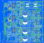
I plan to have a separate PSU on only one board (278mmX288mm), i kept the original Salas UltraBib and adapted the digital PSU. I have already tested the Salas UltraBib separately with succeed.
See first version....I do not know yet if i will use separate enclosure.
Hicoco - That looks like a nice board and another option to use with the pre. Obviously, I have a lot $$ invested already in the current PSU and shunt boards, and would prefer that solution. And make it all fit in my chassis of choice. Is that a board you sell, or if not, could make the gerbers available?
I plan to have a separate PSU on only one board (278mmX288mm), i kept the original Salas UltraBib and adapted the digital PSU. I have already tested the Salas UltraBib separately with succeed.
See first version....I do not know yet if i will use separate enclosure.
I like the packaging a lot. Very nice!
i don't really want to sell them, but if i can share the cost that will be great, actually if i order 5 boards to JLCPCB with 4 Layers(PCB Thickness 1.6, Copper Weight 2oz, with shipping and taxes) that will cost around 40$ each, if i order 10 boards 28$ each.Hicoco - That looks like a nice board and another option to use with the pre. Obviously, I have a lot $$ invested already in the current PSU and shunt boards, and would prefer that solution. And make it all fit in my chassis of choice. Is that a board you sell, or if not, could make the gerbers available?
I have to add the shipping for each board to dispatch at each one (320g)

Hi Paul,
Nice job ! You are fast ! If I remember well I sent you your parcel not too long ago.
Let me check at how I implemented the prescaler on the encoder, it is just a software adjustment, should be quite easy to do, I could even add more settings to accommodate other encoder resolutions.
You mean that now you need to do 4 steps to have 1 increment / decrement?
Right for the fine pitch, DSLR with a macro lens will do, on y side I use this kind of microscope camera and definitely prevent any shorts, I recommend this or similar to one that would value the investment Microscope camera
Alex.
Hi Alex,
Your memory is good, it wasn't too long ago. A direct side effect of having to quarantine.
Thank you for the suggestion, I'll definitely be adding that to my bench after this mess up.
The encoder I have has 32 detents with 32 PPR. When I turn the volume up or down with setting of 1 step:
It requires 4 clicks to go up/down 0.5 dB
It requires 20 clicks to change the submenus (after I press on button #5)
When I try to change the encoder setting in the menu to divide by 4 steps:
It requires 10 clicks to go up/down 0.5 dB
It requires 36 clicks to change the submenus.
It's an odd behaviour since it should normally be correct when using the regular 1 step setting: 1 detent = 1 pulse = 0.5 dB change. I'm starting to wonder if I didn't miss something on the hardware side rather than a software issue?
Paul
Hi Paul,
Indeed it is strange that in the simplest use (adjusting the volume) that you need to have 4 clicks to increase / decrease the volume by 0.5dB...
For the rest it is normal as entering the submenu I make a division on the steps to make it easier to manipulate but still you highlighted a bug that I identified as well last night which is dividing by 5 rather than 4 entering the menu (20 clicks vs. 4 clicks and it should be 16 clicks vs. 4 clicks). I adjusted this already in the FW.
Anyway those are just sub-division of the original encoder step and not a big deal, the main problem is to understand here why you need 4 clicks to go up / down by 0.5dB.
Package received today for Dennis and myself. Thanks Alex and Eric!!!
Thanks Dennis and Twitchie, good to hear 🙂
Thanks for your input. There are some minor wiring clarifications I need, and waiting on Eric06 to address. He mentioned he would publish a simple wiring diagram that show how to go from the 4-pin Phoenix connectors directly to the 3-pin connectors on the shunt PCBs. I need for testing my shunt assemblies. I think it's just a matter of tying the AGNDs together on the logic board. I'm trying to avoid having to use the DB15, but still use the logic board because of it's 5 & 6 volt regulators for the final build. Obviously, there are ways around it to make it all work, but I refer a cleaner solution if possible.
Here it is. 😉
To all, I omitted to keep the 5 pins connections for the analog power through the Salas shunt regulators as well hence the reasons why the connections are not fully point to point.
If you see a mistake, just let me know.
Attachments
Hello Eric,
So when we power up the preamp board from the salas shunt regs we need to bypass R33+D3 and R34+D4? Sorry for asking but didn’t understand.
So when we power up the preamp board from the salas shunt regs we need to bypass R33+D3 and R34+D4? Sorry for asking but didn’t understand.
Yes and it is easy to understand.
If you look at the preamps schematics, these are in the direct path of the power supply rails powering the UGS modules - pretty bad for UGS modules, isn't it.
Best is to solder 2 wire jumpers directly on the back of the PCB in place of these components.
Initially, the serial diodes and resistors where made to protect the on-board regulators powering the muse device.
Here it is. 😉
To all, I omitted to keep the 5 pins connections for the analog power through the Salas shunt regulators as well hence the reasons why the connections are not fully point to point.
If you see a mistake, just let me know.
Perfect. Thanks so much.
Hi Alex,
I looked at the STM32’s encoder A and B inputs on the scope and all appears well. The pins are receiving the correct Gray code from the encoder, yet it seems like it’s ignoring 3/4 states.
It’s quite puzzling. I’ll try with a regular mechanical encoder tomorrow and compare the signals received for both encoders at the STM32’s inputs.
Paul
Hi Paul,
Hold on, I found something and updated the way I handle the encoder.
Could you please check this binary and let me know?
Thanks.
DFU Board1.2 v2.97
Hold on, I found something and updated the way I handle the encoder.
Could you please check this binary and let me know?
Thanks.
DFU Board1.2 v2.97
- Home
- Amplifiers
- Pass Labs
- UGS-muse preamp GB