
Hi Lucian,
I see, yes misunderstood, I thought you were asking about the current.
Yes overall you are correct.
I see, yes misunderstood, I thought you were asking about the current.
Yes overall you are correct.
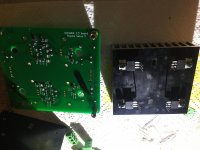
Happily received the boards on Saturday, thank you very much both Alex and Eric. I’m so exited to hear the muse now...
I have started building my main psu and the shunt boards.
Almost everything went smooth. I encountered 2 problems if I can call them so. One is with the chokes which are reversed 180 degrees in the photo in the bom, the schematic is correct so I suppose the footprint is incorrect or maybe I am wrong.
The second thing is that the mouser basket misses 4 x 270r resistors.
For the moment I will play a bit with the shunts and some ugs boards which I have laying around.
As power supplies for the shunts I will use some lithium battery packs. I have a lot of 12s packs and 4 of them will be used here which fit perfectly when getting 32v from the shunts.
Ps. I have added the thermal pads after the photos were taken.
Attachments

@schultzsch - looks nice and please keep the build notes coming. This is a very ambitious build for many of us and these sorts of updates are very helpful.
I have started building my main psu and the shunt boards.
Almost everything went smooth. I encountered 2 problems if I can call them so. One is with the chokes which are reversed 180 degrees in the photo in the bom, the schematic is correct so I suppose the footprint is incorrect or maybe I am wrong.
The second thing is that the mouser basket misses 4 x 270r resistors.
For the moment I will play a bit with the shunts and some ugs boards which I have laying around.
As power supplies for the shunts I will use some lithium battery packs. I have a lot of 12s packs and 4 of them will be used here which fit perfectly when getting 32v from the shunts.
Ps. I have added the thermal pads after the photos were taken.
can you post the basket links please? did i miss them?
thx
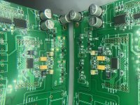
Hi schultzsch, very nice progress and thanks a lot for your feedback.
I do agree for the missing resistors inside the BOM (only 2 per board if I am correct)
These are R4 and R104. I already correct the on-line Mouser basket to make the total qty 20 instead of 18. I still need to update the document itself to reflect this correction.
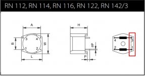
Regarding the orientation of the common mode choke, if I am not mistaken the angled flat on the top of the choke indicates pins 1 and 3 according to the datasheet. I don't see them oriented backward in the 3D picture (angled flat in direction of the rectifier). Agree?
I do agree for the missing resistors inside the BOM (only 2 per board if I am correct)
These are R4 and R104. I already correct the on-line Mouser basket to make the total qty 20 instead of 18. I still need to update the document itself to reflect this correction.
Regarding the orientation of the common mode choke, if I am not mistaken the angled flat on the top of the choke indicates pins 1 and 3 according to the datasheet. I don't see them oriented backward in the 3D picture (angled flat in direction of the rectifier). Agree?
Last edited:
Mouser's basket links are located at the bottom of the pdf BOMs.can you post the basket links please? did i miss them?
thx
Mouser's basket links are located at the bottom of the pdf BOMs.
you mean on hfc forum bom‘s?
Yes those stored at HCFR here: linkyou mean on hfc forum bom‘s?
Each board got its own Mouser's Basket normally.
If there is a particular one you have difficulties with, just let me know.
Ups, my mistake about the chokes. The image is correct.
I used 470r for r13 and r103. For the rest I used 270r.
In the meantime I powered up the shunts and scoped them with a resistive load and also with my ugs modules. Everything is nice and shiny. The negative shunt has a bit more noise than the positive one but still very low.
When I done the order at mouser there were no 220uf caps for the voltage reference thus I ordered and use 330u same type which raises a bit the startup time.
Could you share your wiring diagram from the main PSU to the shunt board - if not using the sub-DB15 connector.
Hi Alex,
I'm finishing a 2 channel build of the UGS Muse and I was wondering if you could add an option for a 32 step encoder. I'm re-using the Grayhill 62A11 optical encoder from my original UGS all-inclusive build.
With the encoder settings to 1 step I need to turn the encoder 4 times to get a change of state, and with the settings to 4 steps I need to turn it 8 times. Given that it an optical encoder that functions like a mechanical one, I've added R23, R24, R36, R37 and C26, C33 as specified for a mechanical encoder (10K and 10nF).
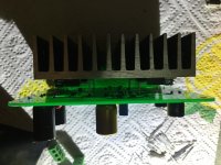
As for the rest of the build, just a bit of a warning for others: I've had a very hard time getting rid of solder bridges with the Muse ICs. I'm not sure why since I usually don't have this sort of problem with other fine pitch ICs. After having burnt 1 Muse (did I overheat it trying to get rid of the small solder balls behind the pins? or did I leave some behind?), I've pulled out a DSLR with a macro lens to make sure I didn't miss any, and I still had some solder stuck behind some pins that I couldn't see with a magnifier (I'm a young padawan, so my eye sight isn't a problem yet and still missed them).
In the meantime, here is a picture of my almost complete UGS Muse to encourage others.
Paul
I'm finishing a 2 channel build of the UGS Muse and I was wondering if you could add an option for a 32 step encoder. I'm re-using the Grayhill 62A11 optical encoder from my original UGS all-inclusive build.
With the encoder settings to 1 step I need to turn the encoder 4 times to get a change of state, and with the settings to 4 steps I need to turn it 8 times. Given that it an optical encoder that functions like a mechanical one, I've added R23, R24, R36, R37 and C26, C33 as specified for a mechanical encoder (10K and 10nF).
As for the rest of the build, just a bit of a warning for others: I've had a very hard time getting rid of solder bridges with the Muse ICs. I'm not sure why since I usually don't have this sort of problem with other fine pitch ICs. After having burnt 1 Muse (did I overheat it trying to get rid of the small solder balls behind the pins? or did I leave some behind?), I've pulled out a DSLR with a macro lens to make sure I didn't miss any, and I still had some solder stuck behind some pins that I couldn't see with a magnifier (I'm a young padawan, so my eye sight isn't a problem yet and still missed them).
In the meantime, here is a picture of my almost complete UGS Muse to encourage others.
Paul
Attachments
Hi Alex,
I'm finishing a 2 channel build of the UGS Muse and I was wondering if you could add an option for a 32 step encoder. I'm re-using the Grayhill 62A11 optical encoder from my original UGS all-inclusive build.
With the encoder settings to 1 step I need to turn the encoder 4 times to get a change of state, and with the settings to 4 steps I need to turn it 8 times. Given that it an optical encoder that functions like a mechanical one, I've added R23, R24, R36, R37 and C26, C33 as specified for a mechanical encoder (10K and 10nF).
As for the rest of the build, just a bit of a warning for others: I've had a very hard time getting rid of solder bridges with the Muse ICs. I'm not sure why since I usually don't have this sort of problem with other fine pitch ICs. After having burnt 1 Muse (did I overheat it trying to get rid of the small solder balls behind the pins? or did I leave some behind?), I've pulled out a DSLR with a macro lens to make sure I didn't miss any, and I still had some solder stuck behind some pins that I couldn't see with a magnifier (I'm a young padawan, so my eye sight isn't a problem yet and still missed them).
In the meantime, here is a picture of my almost complete UGS Muse to encourage others.
Paul
Hi Paul,
Nice job ! You are fast ! If I remember well I sent you your parcel not too long ago.
Let me check at how I implemented the prescaler on the encoder, it is just a software adjustment, should be quite easy to do, I could even add more settings to accommodate other encoder resolutions.
You mean that now you need to do 4 steps to have 1 increment / decrement?
Right for the fine pitch, DSLR with a macro lens will do, on y side I use this kind of microscope camera and definitely prevent any shorts, I recommend this or similar to one that would value the investment Microscope camera
Alex.
Hello,
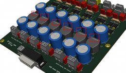
Are there other builders of this project contemplating an integrated configuration, with the PSU inside the pre case? I've been reviewing the overall design, especially the power side and how the logic PCB expects a panel mount exposure to bring all the DC power lines into the pre via the sub-DB15 connector. Actually, it's a clever design, but does require a separate enclosure.
I'm leaning toward putting everything in a single chassis, but that would require tapping off the internal side of the sub-DB15 connector to connect the supply lines from the internal PSU. From the pictures posted on the HCFR site, I can't get a good visual sense of the clearance of all those stacked boards, and what, if any issues, I would run into trying to route power into the inside of the sub-DB15 connector, or their equivalent pins. This approach would be required to keep and use the logic circuitry on the PCB.
If anyone has thought this far ahead yet (or are done), I would be interested in seeing an all-in-one solution. Pictures are work a 1000 words in this case! No pun intended. 🙂
- Home
- Amplifiers
- Pass Labs
- UGS-muse preamp GB