Regarding the output inductor - I recommend you add it before anything else, and mount it near the amplifier output.
One of the problems of having global feedback capacitors is that signals can be injected into the amplifier from pick-up in the output leads.
I'd probably aim for 3uH for the coil (not particularly critical) and a 10 ohm load resistor.
I have not heard any effects from output inductors, but there again, I've not listened to ELS speakers. That is likely to be the only time it may be important to use low values say less than 1uH.
Ok. I will do that. I will put it right at the output fast on connector with just the shortest wire (inch or so) and heat shrink the 10 Ohm and coil. I wish it was built into the board so that it would be neater.Regarding the output inductor - I recommend you add it before anything else, and mount it near the amplifier output.
One of the problems of having global feedback capacitors is that signals can be injected into the amplifier from pick-up in the output leads.
I'd probably aim for 3uH for the coil (not particularly critical) and a 10 ohm load resistor.
I assume this goes for the MX50x2 and all the other LJM designs.
Should I also do the same with the miniJLH or is it unnecessary for the JLH design?
That depends. From what I have seen over the years, those who have used 3-5MHz ft output transistors have not reported any problems. The JLH does not use compensation capacitors but relies on inherent transistor parameters (like Cjc and ft) for stability. So, probably not for that type of JLH build, although if you live near a transmitter it may help if you get RF pickup.
Some, including myself, have tried fast output transistors. Out of two builds, one needed a 33pF capacitor to stabilise against oscillations, which I put in parallel with the feedback resistor. In that case I added an LR/RC output network for the same reasons. The other did not. Other reports I have seen suggest some have needed the capacitors, others not, as well.
I suggest the answer is "if in doubt, add it". I don't think it spoils the frequency response for normal magnetic speaker coils (3.3uH/10 ohms has a 300kHz -3dB point), but may prevent oscillations from pick up or capacitive speaker leads. If you have a fast amp (this particular LJM with 600uA is not "fast" in terms of slewing, I have to say - it begins to run out of steam at 50kHz) then you may want a smaller inductor.
I assume you refer to my earlier suggestion in #7102 of using TIP35 for a direct replacement there, so perhaps I have confused things. I referred to the prototype; MF's XA50 model shown there, which is only 50W/channel AB and quasi complementary. TIP35 should be just fine. The designer's trademark was also to use only standard type silicon power transistors, which is consistent with this and you can recognize his handiwork at other UK audio specialist manufacturers of the time............I'm not convinced that TIP35 would be OK for 100V operation. I take it you have the "C" grade, but the second breakdown point starts at 35V (at least in an old Motorola datahseet: ST don't reveal such useful info). I'd limit it to +/- 40-45V, or use devices with second breakdown limit at 50V. Especially not until you have rewired the diode/resistors, since operating at high voltages with unbalanced currents could easily exceed the second breakdown limit. Remember speakers are not resistive loads, and are mostly an R-L network. Any reactive impedance generates a circular/elliptical load line which can put the output devices into time-limited second breakdown regions.
I've also had problems with ceramic type power resistors. In one amp using 0.47 ohms a temporary overload occurred, fortunately the protection devices saved the amp, but afterwards, the distortion was high. One of the 0.47's had gone high or open. It appeared then that I would have been better using more conventional types, and since I stopped using them I've not had a problem. Don't know if that applies to all manufacturers of that construction.
https://www.musicalfidelity.com/uploads/manuals/English/xa50.pdf
https://www.diyaudio.com/forums/att...fidelity-a50-monoblock-amp-circuit-xa50_2-pdf
The MX50x2 clone is uprated to 100W and has the appropriate semis etc. but frankly, on its tiny and closely packed PCB, I would not rate that as continuous power. I think it would need a very thick heatsink backplate and the thinnest of mica insulators to survive at 100WRMS output in that layout for too long.
Regarding ceramic 5W resistors: For some years now, we've been able to cheaply source 5W ceramics in a thin, vertical mount format like Japanese products from the 1970s onward and shown in kozard's images. The element is a high resistivity alloy ribbon in a Z-folded rather than wound form, for low inductance. However, some square section, axial format types in US, UK and Euro. catalogues, are actually made from moulded spirals of metal oxide compound rather than wire and I think there would be problems trying to maintain a reliable bond to the metal leads if overheated. It's another topic but could this be relevant to your problem? I know AndrewT (R.I.P) had a measure of the problem which pointed to local UK suppliers as one source of non-wire "wound" resistors.
Last edited:
Ian, I wasn't specifically referring to your recommendation, just suggesting that I would not run a TIP35C on 50V rails.
I agree that it is fine for a 50W amp, as this should be able to run on 35V rails. One of my "rules of thumb" is to use devices with second breakdown breakpoints at least the supply rail voltage. Mainly from the point of view of protection.
I have not seen the XA50 circuit before, and as you say the 100W is an inflated version of it. But the designer (or cloner) has kept the same input stage design. Even to maintain the bandwidth of the original, the input stage current should have been increased in relation to the increased voltage swing (slew rate dV/dt=i/C etc), but that may well have changed the stability etc.
I'm still amazed by the classical error of the unbalanced output stage currents. I can only presume, as kozard has found, the manufacturer must have matched the components closely. Re-routing the drivers as discussed should have been mandatory as thermal mismatches in the mounting can start to cause problems. It might have been possible to get away with the design using a single output device, but in such a configuration, I'd have put the 0.22 ohm resistor in the emitter of the output device. If the diode/resistor pair are not rerouted, the only other realistic way of parallelling the devices would have been to add a second pair of low value resistors in the emitters of the lower output transistors, and then just moved the diodes to the collectors. I've never seen industrial equipment parallel transistors or devices without current balancing components.
I agree, too, that the layout isn't really up to 100W. Good layout guys manage to pack components in with minimum board area, but in the case of lots of watts here and there, a bit of space helps.
I never followed up on the ceramic resistor problem. Normally, a failure would demand a root cause investigation, but due to a lack of time and chances that it was construction related, I decided to go back to conventional wire wound (proven) and/or metal oxide resistors. I did not know about the use of moulded spirals of compound, which does not surprise me as being prone to failure compared with an actual metal ribbon or wire.
However, this does show that commercially, developing circuits really needs all those qualifications on parts from suppliers. d-i-y'ers have to rely on reputable distributors for sourcing genuine devices, I think.
Thanks John, for the reply. Not all that much has been said here on parallel CFP output stages; their need for separate drivers and current balance etc. It probably deserves another thread to clarify all the issues from the basics up again, though I expect many professionals would rather not complicate their safer, more predictable world of parallel EF design.
As mentioned earlier, LJM actually warned buyers specifically against the Lusya store's kit of parts for his design, which I believe kozard and I have, since LJM's own store is effectively inaccessible at Taobao, the huge Chinese language online selling platform. I imagine that's why he posts here, to clarify and address kit problems that can't otherwise be managed. I take him at his word as the designer and an honest trader rather than just a competitor for the business, since his comments have proven correct over many years now and this is unique as a means of customer support for Chinese kits and a useful service to the broader DIY community.
As mentioned earlier, LJM actually warned buyers specifically against the Lusya store's kit of parts for his design, which I believe kozard and I have, since LJM's own store is effectively inaccessible at Taobao, the huge Chinese language online selling platform. I imagine that's why he posts here, to clarify and address kit problems that can't otherwise be managed. I take him at his word as the designer and an honest trader rather than just a competitor for the business, since his comments have proven correct over many years now and this is unique as a means of customer support for Chinese kits and a useful service to the broader DIY community.
Last edited:
I received a request (private message) to contact the moderators regarding moving the MX50x2, XA50 and Parallel CFP Output Stages discussion into a new separate thread.
How would I go about doing that?
Perhaps a suitable title (to help others searching for solutions to the same problem) would be:
"Imbalanced Bias Currents, Unmatched Devices and the MX50x2 clone of XA50 with Parallel CFP Output Stage"
How would I go about doing that?
Perhaps a suitable title (to help others searching for solutions to the same problem) would be:
"Imbalanced Bias Currents, Unmatched Devices and the MX50x2 clone of XA50 with Parallel CFP Output Stage"
The title only needs to specify the kit ID and a word or two of any central issue, if there is one. Perhaps "MX50x2 - kit version of Musical Fidelity XA50" says enough. It isn't really a clone in the kit form but does have the general topology. All you need to do is reply to the moderator's message with your acceptance and suggested title. If agreed, they will do the rest and move the thread.
Last edited:
As mentioned earlier, LJM actually warned buyers specifically against the Lusya store's kit of parts for his design, which I believe kozard and I have, since LJM's own store is effectively inaccessible at Taobao, the huge Chinese language online selling platform. I imagine that's why he posts here, to clarify and address kit problems that can't otherwise be managed. I take him at his word as the designer and an honest trader rather than just a competitor for the business, since his comments have proven correct over many years now and this is unique as a means of customer support for Chinese kits and a useful service to the broader DIY community.
I have posted a picture of the board I bought (on LJM thread, not here) and I have asked if mine is genuine. Unfortunately I can not seem to get an answer.
I did not buy from Lusya's store. However there are many many stores of different names that seem to be all the same vendor. Unfortunately on Ebay and Aliexpress it is impossible (as far as I can tell) to figure out who you are buying from. Many storefronts and names seem to be the same vendor. I have ordered item x from one vendor A and item y from vendor B and the next day in my emails I see one was marked shipped at 10:46pm and the other part was marked shipped at 10:47pm. When the two packages arrived the outside box, inside packing material, the printed label (size, font, etc) and the orange color packing tape was identical. The printed label on the box looked identical except the return address/name was different. I am 99% certain they were packed and shipped by the same person. Both boxes in my mail box looked virtually identical and identically packed. (They even arrived the same day.)
And the date code on the transistors on both boards are identical...
Anyways, my board has LJM's new logo and green color which appears to mark his current genuine boards. (In the past he had a different logo and blue color.)
I listened to my first JLH amplifier last night. The left channel has the stock transistors marked TIP41C and the right channel has genuine STM TIP35C from Mouser.
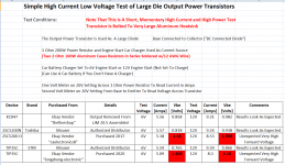
Before soldering in the genuine STM TIP35C I read about fake transistor testors and decided to build a slightly different one oriented towards high current (Class A/JLH).
I had read about another one that tests near the second breakdown region (and I might build that later) but I made a very simple one that is intended to be sensitive to the size of the die and the high current capability of the die.
I did this because many of the fakes seem to have small die with low current capability. And by using a 174V supply and 1M, 100k and 10k resistors it appears to me that many of the small die in the fakes have fairly breakdown voltages.
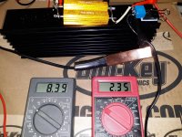
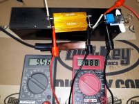
The tester is very simple. The transistor is connected as a Base-Collector connected diode and I use a 10A current source to measure the voltage across the transistor.
Construction only required a large heatsink, scrap 12AWG wire, two 2 Ohm 100W dummy load resistors in parallel (for 1 Ohm resistor) and a 12V power source. A car battery could be used but I used a 12V/6V engine start car charger set to start (not set to charge.)
I have attached pictures of the test and results for genuine TIP35C and 2SC5200. And also for others marked TIP35C and marked 2SC5200 but I suggest you examine the test results... I guess I can't even buy cheap TIP series from anywhere except authorized distributors.
Photos of the TIP35C from Left to Right are: Ebay (Qty 2), Mouser (Qty 2, 2020), Mouser (Qty 2, 2002)
Before soldering in the genuine STM TIP35C I read about fake transistor testors and decided to build a slightly different one oriented towards high current (Class A/JLH).
I had read about another one that tests near the second breakdown region (and I might build that later) but I made a very simple one that is intended to be sensitive to the size of the die and the high current capability of the die.
I did this because many of the fakes seem to have small die with low current capability. And by using a 174V supply and 1M, 100k and 10k resistors it appears to me that many of the small die in the fakes have fairly breakdown voltages.
The tester is very simple. The transistor is connected as a Base-Collector connected diode and I use a 10A current source to measure the voltage across the transistor.
Construction only required a large heatsink, scrap 12AWG wire, two 2 Ohm 100W dummy load resistors in parallel (for 1 Ohm resistor) and a 12V power source. A car battery could be used but I used a 12V/6V engine start car charger set to start (not set to charge.)
I have attached pictures of the test and results for genuine TIP35C and 2SC5200. And also for others marked TIP35C and marked 2SC5200 but I suggest you examine the test results... I guess I can't even buy cheap TIP series from anywhere except authorized distributors.
Photos of the TIP35C from Left to Right are: Ebay (Qty 2), Mouser (Qty 2, 2020), Mouser (Qty 2, 2002)
Attachments
-
 Front of TIP35C Left Ebay Middle Mouser 2020 Right Mouser 2002.jpg1,018.3 KB · Views: 378
 -
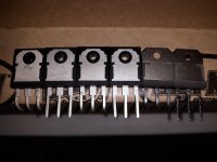 Back of TIP35C Left Ebay Middle Mouser 2020 Right Mouser 2002.jpg762.3 KB · Views: 352
 -
 JLH Output Transistor Test Results.png77.9 KB · Views: 389
 -
 Test of Ebay TIP35C.jpg1,022.8 KB · Views: 341
 -
 Test of Mouser 2020 TIP35C.jpg1,016.1 KB · Views: 325
 -
 Test of Mouser 2002 TIP35C.jpg1 MB · Views: 149
In JLH1969, transistors operate with currents up to
3a\30v. Heat transfer properties are important.
More than Hfe =100 (pair) is desirable.
3a\30v. Heat transfer properties are important.
More than Hfe =100 (pair) is desirable.
I think ST have changed the package recently from The TO-218 to TO-247.
I think you are on the right track for measuring die sizes. But I would not use the BC diode connection, because of quasi-saturation which puts a lot of additional hole current into the base and modulates the conductivity. While the B-C connection gives you a comparative measurement on device resistances, the device will be under extreme operating conditions.
A measure of the thermal resistance might be useful. To measure the thermal resistance, I run the collector from a separate (e.g. 5V) power supply (typically an ex-computer 20A type) and bias the base separately through a resistor. The transistor is directly mounted with thermal grease on a large heatsink of known thermal resistance. Measure the base voltage at a given current, and allow the device to warm up (can take an hour). Measure the base voltage again, and that gives you an indication of the temperature change. If you measure the heatsink temperature that should correlate with the total input power on the device.
You can also get an idea of the actual Vbe: temperature if you also happen to have a power resistor on the heatsink, which you can use to increase the heatsink temperature by a controlled amount and compare the new Vbe.
A measure of the actual saturation voltage may also give a clue to the die size, if you allow the collector voltage to reach saturation using a separate current-limited supply.
And, another clue to the die size are the junction capacitances. Perhaps we need a thread to indicate genuine device Cjc's and Cje's measured at, say, 0V, 5V and 10V (not Cje - max reverse voltage 5V!)
Lastly, I would caution about measuring BVceo/BVcbo using high voltages. Transistors should be able to withstand avalanching BC junctions but in the past, there have been examples of (genunie) devices exhibiting permanent damage presumably because surface states of the device (e.g. in a passivating oxide) around the base-collector junction have become charged, leading to lower breakdown voltages, which are unrecoverable. While I have tested recent devices to be in spec, I've only nudged them on a scope to where the collector starts to increase current significantly, but stopped short of actual breakdown.
Last edited:
Ok. So in keeping with trying to use very simple and readily available components (that what other DIYers might likely have) how about I modify my simple test setup to supply the base through a separate large power resistor (such as an 8 Ohm 100W aluminum cased dummy load) and still supply the collector through the 1 Ohm (two paralleled 2 Ohm 100W aluminum cased dummy loads)?I think you are on the right track for measuring die sizes. But I would not use the BC diode connection, because of quasi-saturation which puts a lot of additional hole current into the base and modulates the conductivity. While the B-C connection gives you a comparative measurement on device resistances, the device will be under extreme operating conditions.
Would that be better? A "roughly" 1.5A current source into the base of what are supposed to be huge D1047, 2SC5200 and TIP35 power transistors?
Then I can add a third volt meter to measure base current and also calculate current gain. I could use an 8 Ohm dummy load in series with anther 2 Ohm dummy load. Then with 10 Ohms into the base and for base current sensing it would make the math/meter reading more intuitive. (Just look at the voltage across the 10 Ohms and divide by 10 to get the current.)
I have been examining the capacitance in a crude fashion with the M328 transistor tester that I have. I simply bend one lead away and first measure BE like was just a diode and then I bend the other lead away and measure BC like it was just a diode.And, another clue to the die size are the junction capacitances. Perhaps we need a thread to indicate genuine device Cjc's and Cje's measured at, say, 0V, 5V and 10V (not Cje - max reverse voltage 5V!)
To measure at 5V and 10V should I try a crude "bias tee" with a 1M resistor to supply bias (such as a 9V battery) and then a 0.1 nF capacitor as block to the capacitance meter?
I am trying to come up with simple tests using everyday DIY equipment such as common volt meters and popular tools such as the M328 transistor tester.
And, another clue to the die size are the junction capacitances. Perhaps we need a thread to indicate genuine device Cjc's and Cje's measured at, say, 0V, 5V and 10V (not Cje - max reverse voltage 5V!)
I have included capacitance in the attached updated results.
I am happy to measure, tabulate and update with other devices (genuine and fake) but I doubt there is anyone out there who wants to donate and mail the genuine devices. Especially since the genuine devices of true interest are often expensive unobtainium.
Attachments

Last edited:
I am trying to come up with simple tests using everyday DIY equipment such as common volt meters and popular tools such as the M328 transistor tester.
As ever, Rod Elliott has done some work in this area. He has a design for a simple but effective transistor tester (Project 31 - Full Featured Transistor Tester).
I built a version that measures with Collector current up to 7 Amps that works very well.
Kozard, where about are you based - country-wise that is?
Cheers
Mike
I am in the US.Kozard, where about are you based - country-wise that is?
I will take a look at Rod Elliott's design although I am likely to only build a simpler subset. Honestly after the measurements I have done (and recent experiences with an assembled Ebay amplifier that burned up) I am likely to just stick with a couple of Toshiba and Sanken part numbers from Mouser and Digikey.
I was ok with the idea of getting something like a UTC or ISC (Inchange Semiconductor Company) clone if they were done reasonably well and if others reported good performance. And I do mean a true clone or generic that is properly and honestly engineered. Not a fake.
However it seems like the 2SC5200 I bought in 2017 and the TIP35C I bought this year are both small low current/low power die. It is interesting that the test results for the 2SC5200 are so similar to the TIP35C. It would have been fun to have a lab to decap and look at the die under a microscope.
What is particularly bothersome is that both the 2SC5200 and the TIP35C came from "top rated" vendors with 99% positive feedback.
Last edited:
OK, the US is a bit far for me to donate any semiconductors 'to the cause': I managed to pick up a batch of MJ15003's a couple of years ago and they turned out (as far as I can see) to be the genuine article.
I also built a simplified version of Rod's tranny tester as I primarily wanted to test hfe with significant current flowing. The biggest hassle was getting transformer, switches etc. rated for 8 Amps or more and putting it in a case.🙂
With regards to Ebay, I tend to take the point of view that sellers there are just 'shifting stuff' to make a living and have no capability of mass testing, or a confident supply chain, so it is always a risk buying from them.
If its important always go to RS, Mouser, Farnell etc. who will jump up and down if they find out that their supply chain is contaminated and have the clout to sort it out.
You said that you listened to your first JLH amp. What version was it and what was your impression so far.
Regards
Mike
Last edited:
You said that you listened to your first JLH amp. What version was it and what was your impression so far.
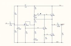
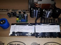
So it is the most basic version which I believe is called the mini1969. I have attached the schematic. It is the tiny little board in the attached photo. Does anyone else have this tiny little JLH?
I have already replaced the stock outputs which were labeled "TIP41". I replaced the right side with two genuine STM TIP35C from Mouser. For the left side I used two 2SC5198 labeled Toshiba from Ebay. As far as capacitance and high current base-collector connected diode characteristics go they might actually be genuine devices.
For initial impressions I think it shines on female vocals and piano as two examples.
However for dense/louder mixes such as hard rock I think there is too little power and/or too much distortion.
I am currently considering modifications and upgrades to this mini1969 first. If I end up suitably impressed then I can invest in a better JLH version. So far I have changed the outputs and next I can look into improving the power supply (there are no power supply caps on these little boards) and the output cap. I should also investigate the biasing soon, I think. Biasing might involve replacing two resistors on this particular version among other things.
I will also ask for suggestions on what improvements can be tried on this little board before I consider a more expensive JLH. (A large board Zero Zone with on board caps and Sanken PNP outputs was one that was recommended to me.)
I might go as far as reversing all component polarities on one of these little boards and installing two 2SA2223 Sanken (from Digikey). If I like that then I might try that Zero Zone board.
But I was also wondering if I should try a JLH version with MOSFET output devices next. (Too many choices to explore 🙂)
This week I plan to work on the caps (mainly adding solid Vcc bypassing on the board and a larger output cap).
Attachments
Last edited:
I don't think that's quite the right type of driver/splitter transistor (Q2) there either, which casts serious doubt on those alleged TIP41 transistors, if they also work satisfactorily in the role. The genuine articles are or rather were, good for up to 4W as output and current source transistors but I don't think there is any sure way of predicting the performance or likely problems among the many and various types of fakes out there.
It would be prohibitively expensive and time consuming to track down the original semis and specific component types to compare the original design with whatever we can concoct today but at least we can work with known spec, genuine semis as substitutes and that can give indications of what JLH was actually talking about, back in the day.
Genuine TIP41 are cheap enough items to start with and Q2 could be any of a number of small, fast audio drivers, as it happens. FWIW, I had good results with obsolete but genuine Hitachi 2SD669 and there are specified Chinese copies of the latter available quite cheaply in T092L or TO126 outline from profusion PLC (UK) Transistors (Buy Online) | Profusion.
Profusion supply professional audio repairers with original and substitute parts so I don't think they will be selling you the same trash as the retail platform kit sellers in China.
Well I have a few genuine Toshiba TTC004 left over from fixing the MX50x2. Are those suitable?
I also have two genuine STM TIP41C I purchased from Mouser in 2002 for a different purpose.
Finally I have a bag of 2SD669 but I can not tell you what is really inside the package for those.
Which one is the best choice?
By the way I just added a 1000 uF 50V Nichicon VX and 0.33 uF MKP to the Vcc and GND screw terminal pins on the bottom of the board since there are no Vcc caps on these little boards. I think that improved the sound a bit. Tomorrow I plan to put a larger cap very close to the board with a short wiring harness. The 1000 uF is about as large as can be mounted on/under these tiny boards unless I get a different series or lower voltage capacitor which is physically smaller.
- Home
- Amplifiers
- Solid State
- JLH 10 Watt class A amplifier