Per
After the uncalled for bit of nastiness from the troll
I have always felt that the Rotel 991 was for some inexplicable reason lacking some magic which your changes along with the work of Paulus will unlock. My electronic knowledge is not even enough beyond changing components as instructed or for different types e.g. film caps resistor types etc. Many many years ago I had access to lab equipment but sadly no more I built my amp based on the graham nalty virtuoso in ETI and modified some cdp and sacd players, built a battery powered dac etc.
But I have done little original circuit design and so I am grateful for people like you who are willing to put there own hard work on here with clear explanations.
Thanks
Anjum
I don't consider dreamth to be a troll, he has made some valid points - and anyway, what would a troll be doing here? In fact I don't think there are any proper trolls on this blog. (Not even anyone linking to foreign gorgeous women seeking marriage, etc.)
But there are definitely people with thin skins and hot tempers which both are bad traits if you want to successfully restore or upgrade old amplifiers.
It is all too easy to hide behind and attack online aliases, which is why I always sign my posts with my real name, the AP halo just protects my alias.😉
To your point re the RB-991. All Rotels (ok, maybe not the very old STK IC module output ones) have the potential to sound, well, less 'Rotelesque' and more like a much more expensive, precise high end audio amp with just a few changes.
And Paulus would tell you that it is so and can actually be done without deep electronic knowledge (although your heart rate may go up a bit during the process).
Per
My real name is Anjum., I had to pick a variation as anjum was already taken along with anjump etc. I am on other forums as anjum eg. jaguarforums and uksaabs
My other hobby, and the most time consuming! at the moment, is restoring old classic cars. I have a classic Saab 900, a wreck of a jaguar xjc in the midst of complete rebuild including a massive amount of welding and a 78 transam pontiac firebird in bits!
In my hifi list of projects is to implement the i2soverusb board into my battery powered pcm63k dac, rebuild my virtuoso power amp, build a jfet based active crossover, modify the martin logans, and setup a pc based music library and now thanks to you and Paulus upgrade my Rotel!! My heartrate always goes up when I blow up expensive output devices (mj11015/6) repeatedly probably due to buying fake ones from ebay. I'm now trying to decide whether to buy them from farnell, replace them with
2SD2390/2SB1560 (cheaper faster designed for audio) or change to mosfets, the circuit was originally changed by graham to use mosfets RFM10N15/rfm10P15 now extinct and superceded.
I like the virtuoso sound and design as it has no electrolytics in the signal or feedback path and sounded better than the rotel. plus it's got some personal attachment as I've spent years and many hours rebuilding and improving it.
...... with just a few changes.
And Paulus would tell you that it is so and can actually be done without deep electronic knowledge (although your heart rate may go up a bit during the process).
Per
They are, in fact, a few changes......i believe we made 4 of them

The only problems i had with the 991's is that they are not easy to service.
Both of the channel/pcb's are placed vertically with virtually no room to play.
Pull them out completely so they are easy accessible.....
If your amps haven't been serviced for more then 10 years, replace the psu capacitors as well.
They are available via Rotel service, they where offered to me for about 45 euro's each, i bought aftermarket's.
My advice would be, with the positive outcome remarks in the back of your head, if you are ready to upgrade, do all the upgrades at once.
Take your time, it isn't something to do on the side.
Don't drink coffee before this job 😀 and by the way, Per's heart rate comments are spot on.
Check everything once then check again and before switching on, check again.
You won't be disappointed with the sound of your "new" 991's
Good luck!! Paulus
Hi ! first of all thank you so much for this extremely valuable thread.
I have some questions:
is there a way to reduce the 50Hz noise maybe ?
I read about issues related to balance control ... why not bypass it ?
And the tone controls are not likely to worsen the figures when engaged ? so why to keep them ?
Is all the gain in the 1st op-amp really needed ? if i am not wrong the amp stage has already a voltage gain = 18 times.
I am very interested in the 820ax mods having one myself. I see that the discussion on this amp stops earlier in the thread.
Thanks a lot again.
Hi again.
I had planned to do a resume or a "how to" based on the things I currently do in the upgrades of the Rotels. It differs a bit from where this thread started, as I have constantly tried to keep everything as simple as possible so that people without extensive electronic/mechanical tools and skills could give it a go. (And also because I am really a lazy plonker).
But I never got 'round to doing it.😱
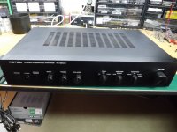
Until now, as alp1961 wanted me to upgrade his RA-820AX and sent it up to me from Portugal. It is really a "beauty of a beast" in really mint cosmetic condition, see pics.
And he agreed that I could stage and post the upgrade steps on the thread.
At least that's the plan - and it would take this thread back on topic. Stay tuned.
Per
Attachments

My real name is Anjum., I had to pick a variation as anjum was already taken along with anjump etc. I am on other forums as anjum eg. jaguarforums and uksaabs
My other hobby, and the most time consuming! at the moment, is restoring old classic cars. I have a classic Saab 900, a wreck of a jaguar xjc in the midst of complete rebuild including a massive amount of welding and a 78 transam pontiac firebird in bits!
In my hifi list of projects is to implement the i2soverusb board into my battery powered pcm63k dac, rebuild my virtuoso power amp, build a jfet based active crossover, modify the martin logans, and setup a pc based music library and now thanks to you and Paulus upgrade my Rotel!! My heartrate always goes up when I blow up expensive output devices (mj11015/6) repeatedly probably due to buying fake ones from ebay. I'm now trying to decide whether to buy them from farnell, replace them with
2SD2390/2SB1560 (cheaper faster designed for audio) or change to mosfets, the circuit was originally changed by graham to use mosfets RFM10N15/rfm10P15 now extinct and superceded.
I like the virtuoso sound and design as it has no electrolytics in the signal or feedback path and sounded better than the rotel. plus it's got some personal attachment as I've spent years and many hours rebuilding and improving it.
Tread lightly if you want to change to MOSFETS. I built an amp using Exicons, but getting stability using Miller compensation was very difficult. This is why Erno used VAS dominant pole filtering in all his designs.
alp1961 wanted me to upgrade his RA-820AX and sent it up to me from Portugal. It is really a "beauty of a beast" in really mint cosmetic condition, see pics.
And he agreed that I could stage and post the upgrade steps on the thread.
At least that's the plan - and it would take this thread back on topic. Stay tuned.
Per
Hi there Per, you are quickly becoming the Rotel expert in the EU 😀 orders in from Portugal

Interested to see and learn what you are going to do with this really beautiful amp, it is practically a new one 😱
Cheers, Paulus
Before starting the upgrade:
Off with the top cover (six screws and slides back). Inside it is dusty, but not too bad and could relatively easily cleaned up when the components that need to be replaced are gone.
Power on (with finger ready on the off switch), but no smoke or visible problems. Nothing runs very warm.
First some initial DMM measurement checks (all shown as L/R):
Output offsets at speaker terminals: 78mV / 72mV
Bias setting: 4.2mV / 5.0mV
Supply voltages: +/-39.9V ripple: 48mVac / 34mVac
Regulated supply: +20V / -19.5V ripple less than 0.1mVac
All these measurements are not unusual for an old Rotel.
First listening test:
(Nicked borrowed daughter’s mp3 player) and put on headphones – at least both channels work, but no impressive detail - sound a bit soft and bland even for a mp3.
But anyway, so far so good.
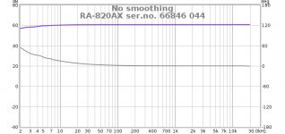
Then on to pre-update linearity (SPL and Phase) and RTA distortion (THD):
Linear from about 5Hz and up (blue trace), but phase already starts to increase below 300Hz (grey trace).
1kHz THD (L/R): 0.058% / 0.31% (!) - mainly 2nd harmonic.
Oops, something is not right. (Spec is <0.03%)
Time for some serious TLC and upgrades for this nice looking RA-820AX!
Stay tuned.
Per
Off with the top cover (six screws and slides back). Inside it is dusty, but not too bad and could relatively easily cleaned up when the components that need to be replaced are gone.
Power on (with finger ready on the off switch), but no smoke or visible problems. Nothing runs very warm.
First some initial DMM measurement checks (all shown as L/R):
Output offsets at speaker terminals: 78mV / 72mV
Bias setting: 4.2mV / 5.0mV
Supply voltages: +/-39.9V ripple: 48mVac / 34mVac
Regulated supply: +20V / -19.5V ripple less than 0.1mVac
All these measurements are not unusual for an old Rotel.
First listening test:
(
But anyway, so far so good.
Then on to pre-update linearity (SPL and Phase) and RTA distortion (THD):
Linear from about 5Hz and up (blue trace), but phase already starts to increase below 300Hz (grey trace).
1kHz THD (L/R): 0.058% / 0.31% (!) - mainly 2nd harmonic.
Oops, something is not right. (Spec is <0.03%)
Time for some serious TLC and upgrades for this nice looking RA-820AX!
Stay tuned.
Per
Attachments


Last edited:
RA-820AX upgrade revisited
Firstly, please note that I do not consider myself as ”the” expert and the upgrade choices and techniques that I make are not the gospel.
Thus, I would welcome and encourage others on this thread to suggest other/better ways to do things or components to use, as I intend to always keep learning.
Upgrades: Always turn off the amp and pull the mains plug before starting.
The RA-820AX schematic can easily be found on the web, I find it useful to have a printed copy on the desk as reference and to note down the changes as I go along.
I normally work my way clockwise around the amp, starting with the power section.
Also, I remove the front panel (seven screws and pull the LED connector, panel pulls off easily). The reason being that any small hard particle or clipping on the workbench will give a visible mark on the anodized black edges of the front panel – and you will be turning the amp over many times (and you will also more easily get to clean the panel from dirt – use mild liquid soap and a soft sponge gently, otherwise the screen printed lettering comes off easily).
But this means that you will no longer get a visual ON indication from the LED, hence the above safety advice.
Stage 1: Power supply
The mains transformer will eventually be replaced with a toroidal, but for now I’ll leave the old E-core type in. Actually, replacing the tranny is optional for this upgrade as it involves soldering in the 240Vac mains voltage area. Some may not feel confident with that – for good reasons.
I remove all fuses, check their value and clean them, their holders and the pcb around them and replace. Then remove the bottom panel (8 screws around the edge and two M3 in the middle). It is good practice to keep all screws removed in a small container or plastic bag, they tend to easily roll away and go walkabout.
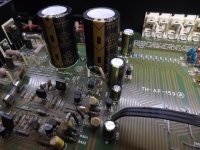
Then to the two big reservoir capacitors. Unsolder and remove the old, clean up the pcb and replace with new, larger caps. I use ELNA LAO’s 10,000[FONT=FreeSans, sans-serif]µ[/FONT]F 63V – other brands are available, but in my mind there is not much to be gained to go for eg. Mundorf’s at £££ a piece.
Before pushing the caps in secure them with a bead of non-corrosive glue or silicone on the cap bottom perimeter at the pcb interface. I use Dow 3140. Push in and solder the new caps.
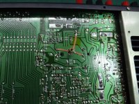
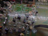
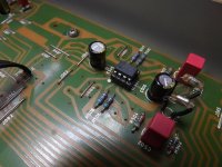
The layout of the 35[FONT=FreeSans, sans-serif]µ[/FONT]m pcb copper ground tracks are not good enough for proper hum rejection because of the very large currents that flow there. I use two broad 2.5mm solder wick copper mesh strips to beef up the conductivity, first extra securing any tracks that are crossed with some Kapton tape. See pic.
This ’milli-Ohmly’ connects the two cap ground pins and the transformer black wire pin to the ground star point.
Now on to the regulator circuit that produces the +/-20Vdc to the preamps. I plan to replace the preamp’s old NE3342s with OPA2134s (or LME49720s) – and they need to keep their supplies well below 18V. Unsolder and pull both zeners and the four capacitors (D901/2, C907/8/9/10). Clean the pcb.
I replace with 17V zeners to get a safe +/-16.5V and Panasonic FM 100[FONT=FreeSans, sans-serif]µ[/FONT]F and 470[FONT=FreeSans, sans-serif]µ[/FONT]F’s (actually 1000[FONT=FreeSans, sans-serif]µ[/FONT]F, as I was out of 470’s). Other ultra low ESR cap types would also do.
That’s it – stage 1 completed. Now turn the amp and DMM on and check that the reg voltages (easiest done on the jumpers leading to the phono preamp) are about +/- 16.5V.
Crack open a beer or have a strong cup of tea to get the heart rate down again before the next stage.
TBC.
Per
Firstly, please note that I do not consider myself as ”the” expert and the upgrade choices and techniques that I make are not the gospel.
Thus, I would welcome and encourage others on this thread to suggest other/better ways to do things or components to use, as I intend to always keep learning.
Upgrades: Always turn off the amp and pull the mains plug before starting.
The RA-820AX schematic can easily be found on the web, I find it useful to have a printed copy on the desk as reference and to note down the changes as I go along.
I normally work my way clockwise around the amp, starting with the power section.
Also, I remove the front panel (seven screws and pull the LED connector, panel pulls off easily). The reason being that any small hard particle or clipping on the workbench will give a visible mark on the anodized black edges of the front panel – and you will be turning the amp over many times (and you will also more easily get to clean the panel from dirt – use mild liquid soap and a soft sponge gently, otherwise the screen printed lettering comes off easily).
But this means that you will no longer get a visual ON indication from the LED, hence the above safety advice.
Stage 1: Power supply
The mains transformer will eventually be replaced with a toroidal, but for now I’ll leave the old E-core type in. Actually, replacing the tranny is optional for this upgrade as it involves soldering in the 240Vac mains voltage area. Some may not feel confident with that – for good reasons.
I remove all fuses, check their value and clean them, their holders and the pcb around them and replace. Then remove the bottom panel (8 screws around the edge and two M3 in the middle). It is good practice to keep all screws removed in a small container or plastic bag, they tend to easily roll away and go walkabout.
Then to the two big reservoir capacitors. Unsolder and remove the old, clean up the pcb and replace with new, larger caps. I use ELNA LAO’s 10,000[FONT=FreeSans, sans-serif]µ[/FONT]F 63V – other brands are available, but in my mind there is not much to be gained to go for eg. Mundorf’s at £££ a piece.
Before pushing the caps in secure them with a bead of non-corrosive glue or silicone on the cap bottom perimeter at the pcb interface. I use Dow 3140. Push in and solder the new caps.
The layout of the 35[FONT=FreeSans, sans-serif]µ[/FONT]m pcb copper ground tracks are not good enough for proper hum rejection because of the very large currents that flow there. I use two broad 2.5mm solder wick copper mesh strips to beef up the conductivity, first extra securing any tracks that are crossed with some Kapton tape. See pic.
This ’milli-Ohmly’ connects the two cap ground pins and the transformer black wire pin to the ground star point.
Now on to the regulator circuit that produces the +/-20Vdc to the preamps. I plan to replace the preamp’s old NE3342s with OPA2134s (or LME49720s) – and they need to keep their supplies well below 18V. Unsolder and pull both zeners and the four capacitors (D901/2, C907/8/9/10). Clean the pcb.
I replace with 17V zeners to get a safe +/-16.5V and Panasonic FM 100[FONT=FreeSans, sans-serif]µ[/FONT]F and 470[FONT=FreeSans, sans-serif]µ[/FONT]F’s (actually 1000[FONT=FreeSans, sans-serif]µ[/FONT]F, as I was out of 470’s). Other ultra low ESR cap types would also do.
That’s it – stage 1 completed. Now turn the amp and DMM on and check that the reg voltages (easiest done on the jumpers leading to the phono preamp) are about +/- 16.5V.
Crack open a beer or have a strong cup of tea to get the heart rate down again before the next stage.
TBC.
Per
Attachments
Hi Per,
Wow 😱, this is very instructive and enlightening for me. It's due to the lack of this level of detail that I never ventured into a project like this.
Thanks for all the effort and patience.
Cheers,
Rui
Wow 😱, this is very instructive and enlightening for me. It's due to the lack of this level of detail that I never ventured into a project like this.
Thanks for all the effort and patience.
Cheers,
Rui
Hi again. I had planned to do a resume or a "how to" based on the things I currently do in the upgrades of the Rotels. It differs a bit from where this thread started, as I have constantly tried to keep everything as simple as possible so that people without extensive electronic/mechanical tools and skills could give it a go ... Per
Hi ! thank you so much for your very kind and extremely valuable project.
I truly think that almost ANY amp can be upgraded. Especially cheap amps where the limited budget does not allow for better parts or techniques.
A so so sounding amp can be made decent sounding ... and an already good sounding one can be made very very good sounding. The difficult is in doing that ... very interesting thread indeed.
Before starting the upgrade:
... Then on to pre-update linearity (SPL and Phase) and RTA distortion (THD): Linear from about 5Hz and up (blue trace), but phase already starts to increase below 300Hz (grey trace).
1kHz THD (L/R): 0.058% / 0.31% (!) - mainly 2nd harmonic.
Oops, something is not right. (Spec is <0.03%)
Time for some serious TLC and upgrades for this nice looking RA-820AX!
Stay tuned. ----
... Stage 1: Power supply .... Per
Very very interesting. Thank you. Do you intend to perform the measurements also on the unit after the PS mods ?
I am always in conflict ... my heart tells me to just listen to the sound ... my brain instead wants to see the figures ... the THD graphs.
I turly think that noise and distortion are not a good thing to have in a unit designed and built to playback faithfully what is in the recording.
It would be very interesting to see if this first mod can already tame that 50Hz noise peak.
If not would it be possible to insert some kind of passive filtering before or after the big PS caps ? like two L or R ? i am not an expert
Again i will be following this thread with the greatest interest
Thank you so much again 🙂
Last edited:
RA-820AX upgrades revisited
I should add that anyone that doesn’t quite follow or understand the why’s and how’s – please do ask questions, I may not be able to answer all, but there are definitely people on the thread that can.
How does the old saying go? ”He who asks a question may seem ignorant for a minute – he who doesn’t ask remain so for the rest of his life”. (Ok, make that he/she, sorry ladies). So please fire away!
Stage 2: Preamps.
These are probably the easiest stages to upgrade, only 7 components to switch in the phono circuit and 5 in the preamp.
If you are absolutely sure that you will never ever play a vinyl record, you can of course leave the phono stage as is, but I always do the full Monty.
Phono RIAA circuit:
I replace the 100[FONT=FreeSans, sans-serif]µ[/FONT]F’s (C414/15) with FM’s, the 10[FONT=FreeSans, sans-serif]µ[/FONT]F (C403/04) with 22[FONT=FreeSans, sans-serif]µ[/FONT]F FM’s and the 10[FONT=FreeSans, sans-serif]µ[/FONT]F output C411/12 with 1[FONT=FreeSans, sans-serif]µ[/FONT]F WIMA film – moving the low frequency roll-off outside of the RIAA de-emphasis circuit.
Then, (perhaps most controversially) I replace the NE5532 with an OPA2134 or OPA2604.
Some argue that because most vinyl records were recorded through NE5532’s they should be played through the same. I beg to differ. The input bias current in the NE5532 is atrociously high by today’s sandard, and the stage is DC coupled to the pickup stylus, so you will have a standing current through this sub-mV magnetic sensor/generator which is not good.
The FET input OPA’s have pA bias currents, and will merely sit as low noise ”sniffers” on the weak pickup signal. And the sound is better for it IMHO.
But, I always put in a quality IC socket so the user can more easily switch back or to another opamp.
Preamp:
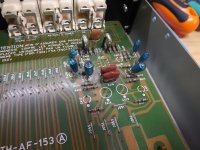
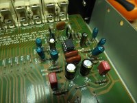
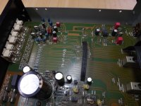
Again I replace the 100[FONT=FreeSans, sans-serif]µ[/FONT]F’s (C505/06) with FM’s as above, the input 10[FONT=FreeSans, sans-serif]µ[/FONT]F’s (C501/02) with 4.7[FONT=FreeSans, sans-serif]µ[/FONT]F WIMA’s and then another OPA2134.
This time I choose it because of that amp’s low offset which will allow us to DC-couple between the preamp and the power stage input, eliminating the two last remaining electrolytic capacitors in the signal path (C601/02). See pics.
(The schematic shows two 100[FONT=FreeSans, sans-serif]µ[/FONT]F (C505/06) at the output of the preamp, but they were not mounted in this amp – nor should they be.)
And that is stage 2 done. Getting more confidence? Good, as you will need it for stage 3.😉
Per
I should add that anyone that doesn’t quite follow or understand the why’s and how’s – please do ask questions, I may not be able to answer all, but there are definitely people on the thread that can.
How does the old saying go? ”He who asks a question may seem ignorant for a minute – he who doesn’t ask remain so for the rest of his life”. (Ok, make that he/she, sorry ladies). So please fire away!
Stage 2: Preamps.
These are probably the easiest stages to upgrade, only 7 components to switch in the phono circuit and 5 in the preamp.
If you are absolutely sure that you will never ever play a vinyl record, you can of course leave the phono stage as is, but I always do the full Monty.
Phono RIAA circuit:
I replace the 100[FONT=FreeSans, sans-serif]µ[/FONT]F’s (C414/15) with FM’s, the 10[FONT=FreeSans, sans-serif]µ[/FONT]F (C403/04) with 22[FONT=FreeSans, sans-serif]µ[/FONT]F FM’s and the 10[FONT=FreeSans, sans-serif]µ[/FONT]F output C411/12 with 1[FONT=FreeSans, sans-serif]µ[/FONT]F WIMA film – moving the low frequency roll-off outside of the RIAA de-emphasis circuit.
Then, (perhaps most controversially) I replace the NE5532 with an OPA2134 or OPA2604.
Some argue that because most vinyl records were recorded through NE5532’s they should be played through the same. I beg to differ. The input bias current in the NE5532 is atrociously high by today’s sandard, and the stage is DC coupled to the pickup stylus, so you will have a standing current through this sub-mV magnetic sensor/generator which is not good.
The FET input OPA’s have pA bias currents, and will merely sit as low noise ”sniffers” on the weak pickup signal. And the sound is better for it IMHO.
But, I always put in a quality IC socket so the user can more easily switch back or to another opamp.
Preamp:
Again I replace the 100[FONT=FreeSans, sans-serif]µ[/FONT]F’s (C505/06) with FM’s as above, the input 10[FONT=FreeSans, sans-serif]µ[/FONT]F’s (C501/02) with 4.7[FONT=FreeSans, sans-serif]µ[/FONT]F WIMA’s and then another OPA2134.
This time I choose it because of that amp’s low offset which will allow us to DC-couple between the preamp and the power stage input, eliminating the two last remaining electrolytic capacitors in the signal path (C601/02). See pics.
(The schematic shows two 100[FONT=FreeSans, sans-serif]µ[/FONT]F (C505/06) at the output of the preamp, but they were not mounted in this amp – nor should they be.)
And that is stage 2 done. Getting more confidence? Good, as you will need it for stage 3.😉
Per
Attachments
Very very interesting. Thank you. Do you intend to perform the measurements also on the unit after the PS mods ?
I am always in conflict ... my heart tells me to just listen to the sound ... my brain instead wants to see the figures ... the THD graphs.
It would be very interesting to see if this first mod can already tame that 50Hz noise peak.
If not would it be possible to insert some kind of passive filtering before or after the big PS caps ? like two L or R ? i am not an expert
Ah, that would probably have been a good idea, but I got a bit carried away - as usual. It may have given a clue as to what caused the high distortion, but it wouldn't have made me stop the upgrade anyway.
Don't pay too much attention to the 50/100Hz peaks on the chart, it is an artifact within my measurement system - I get it on all amps I test, even the very high end types.
I have tried to put each of my high sensitivity meters and scopes on the signal - and there is nothing of that peak magnitude to be seen. Listening closely through high quality headphones also confirms this. No hum!
As per the good advice from sgrossklass I am preparing to make an instrumentation amp circuit in front of the XonarU7 input, hoping that this would improve things. (I can't afford an Audio Precision device.)🙁
But thank you for your kind words.🙂
Per
This dissolves my doubts. Actually it looked a little abnormal. FWIU there can very well be some AC ripple but considering the diode bridge in between it should be located at a Hz double the 50-60 Hz ? but your words explain all 🙂... Don't pay too much attention to the 50/100Hz peaks on the chart, it is an artifact within my measurement system - I get it on all amps I test, even the very high end types.
I have tried to put each of my high sensitivity meters and scopes on the signal - and there is nothing of that peak magnitude to be seen...
You are welcome. I am slow at catching things but i am finding your directions extremely educational. And very very interesting.... But thank you for your kind words.🙂 Per
Kind regards, gino
Hello all, I’m looking to upgrade my RB960BX and sorry in advance of this thread is on a specific model. The power supply caps are 4- 10,000 uf 50 volt caps. Was thinking of going with a 63 volt but looked at mine and it looks like they have three legs on them. Does this sound right? I can’t find any three legged snap in caps.
You should be able to fit two-pin snapfit caps if you study the pcb layout. Most of the three or more pins are just for mechanical strength anyway. Do make double sure of the cap orientation and polarity - they are seriously nasty firecrackers if you put them in the wrong way round.
Per
Per
... As per the good advice from sgrossklass I am preparing to make an instrumentation amp circuit in front of the XonarU7 input, hoping that this would improve things... Per
Sorry, you mean that you have the noise even with no input to the Xonar U7 ? this is quite strange. From what i read in the net the Xonar is a very decent sound card. i read 114dB SNR 🙄 You should get a very even and low noise floor with U7 inputs shorted/open
I am using a quite cheaper Terratec soundcard (i guess not on par with your U7) and i do not get much noise at all. Strange. 😕
ASUS Xonar U7 — MAC/DIY
Last edited:
RA-820AX upgrades revisited
P.S. re: Preamp
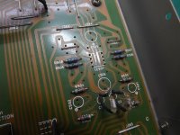
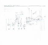
Please note that there is (one of the rare) serious error in Rotel’s schematic.
The two 100[FONT=FreeSans, sans-serif]µ[/FONT]F (C505/6) shown as connected to the opamp’s output pin 7 – is on the pcb in fact the decoupling capacitors between V+ (pin 8) and V- (pin 4) and ground, respectively.
DO NOT short these – or there will be smoke and tears!
Per
P.S. re: Preamp
Please note that there is (one of the rare) serious error in Rotel’s schematic.
The two 100[FONT=FreeSans, sans-serif]µ[/FONT]F (C505/6) shown as connected to the opamp’s output pin 7 – is on the pcb in fact the decoupling capacitors between V+ (pin 8) and V- (pin 4) and ground, respectively.
DO NOT short these – or there will be smoke and tears!
Per
Attachments
that "atrociously" high bias current is actually doing already what your 10uf to 1uf capacitor change does...by the way...the 1uf Wima might exhibit some microphony compared to the original electrolitic.I'd try a 100v film cap there, fks or fkp, fks preffered, but generally i bet a nichicon muse cap of original value works better there.opa134 max supply is +-18v and your lose capacitor multiplier is giving +-17.3v depending on the zener diode tight specs.NE5532 is +-22v..Phono RIAA circuit:
I replace the 100[FONT=FreeSans, sans-serif]µ[/FONT]F’s (C414/15) with FM’s, the 10[FONT=FreeSans, sans-serif]µ[/FONT]F (C403/04) with 22[FONT=FreeSans, sans-serif]µ[/FONT]F FM’s and the 10[FONT=FreeSans, sans-serif]µ[/FONT]F output C411/12 with 1[FONT=FreeSans, sans-serif]µ[/FONT]F WIMA film – moving the low frequency roll-off outside of the RIAA de-emphasis circuit.
Then, (perhaps most controversially) I replace the NE5532 with an OPA2134 or OPA2604.
Some argue that because most vinyl records were recorded through NE5532’s they should be played through the same. I beg to differ. The input bias current in the NE5532 is atrociously high by today’s sandard, and the stage is DC coupled to the pickup stylus, so you will have a standing current through this sub-mV magnetic sensor/generator which is not good.
The FET input OPA’s have pA bias currents, and will merely sit as low noise ”sniffers” on the weak pickup signal. And the sound is better for it IMHO.
But, I always put in a quality IC socket so the user can more easily switch back or to another opamp.
Per
Last edited:
"that "atrociously" high bias current is actually doing already what your 10uf to 1uf capacitor change does."
Sorry, you need to elaborate a bit more on that point. IMHO, having a constant current through the stylus micro magnet is more akin to taking away the anti-skating on the PU arm. It doesn't constitute a high pass filter.
On your other points, note that the output capacitor has a very low impedance (the opamp output) on one side, giving any microphony interference a really hard time.
In fact, with a low offset OPA2134 you could probably get away with removing the entire output trio: R415/C411/R417. I might just try that.
Per
Last edited:
The current bias through the magnetic core of a catridge will do what any dc bias does ...lower the ability to respond at the lowest frequencies although at that level i can bet it's barely noticeable and if the cartridge wiring is done as in humbucking pick-up(mm carts have 4 magnetic cores and 4 crossed coils ) the dc bias will not act at all on the cartridge. As for complete dc response at power on and power off amp's output state becomes critical for the speakers health... As for the antiskating you can do it anyway after power up, but i fully doubt that the cartridge magnetization will unbalance the tonearm usual loading.
Last edited:
- Home
- Amplifiers
- Solid State
- Improve a Rotel amp THD by 20dB!