Maybe you can show your output stage schematic.
In many cases "single ended" output stage will be worse than a non perfectly matched n and p devices stage, when they run under the same current. "Single ended" stage is more far from symmetry.
In many cases "single ended" output stage will be worse than a non perfectly matched n and p devices stage, when they run under the same current. "Single ended" stage is more far from symmetry.
Output is simple single opamp instrumentation amplifier. gain of 1, 10k resistors.
I thought you perhaps tried everything as you make updated versions for years.
Later I will try it.
What about the supergain blocks from LT AN67 ?
I thought you perhaps tried everything as you make updated versions for years.
Later I will try it.
What about the supergain blocks from LT AN67 ?
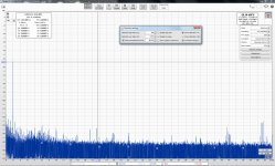
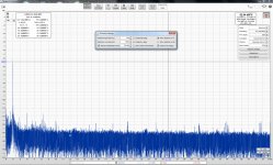
REW switched to decibels
passive notch -53dB + insertion loss
60 dB post amplifier
still everything unshielded
passive notch -53dB + insertion loss
60 dB post amplifier
still everything unshielded
Attachments

Last edited:
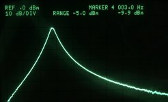
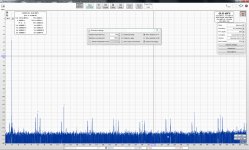
35.5 Vrms fundamental 😱
Yes, maybe I do something wrong ?
I increase the manual fundamental until it shows me -53dBc which is my notch depth.
source R+S UPA3 generator
soundcard -22dbfs
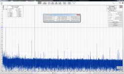
1) 118mV into notch and post amplifier
2) 573mV into passive bandpass, notch and post amplifier /the 0,000081 was in a good moment, most of the time it was around 0,00011
see how the bandpass cleans up the signal 🙂
Notice the required manual fundamental voltage to have the 4khz at -54dbc
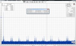
soundcard -22dbfs
1) 118mV into notch and post amplifier
2) 573mV into passive bandpass, notch and post amplifier /the 0,000081 was in a good moment, most of the time it was around 0,00011
see how the bandpass cleans up the signal 🙂
Notice the required manual fundamental voltage to have the 4khz at -54dbc
Attachments
Last edited:

It appears to have an IM product and best guess is around 500 Hz. Something in either the card, the source or most likely common mode element has a significant 500 Hz component. You are band limiting the measurement at 500 Hz which may suppress the source of the modulation. These measurements are really hard to do cleanly. The first 100 dB not so much but below that you need to work really hard on the setup. I much prefer dB to % because with these numbers your counting zeros and there are lots to count. And dB relate better to the task of reducing interference and harmonics.
LME is classA ?
Every opamp is class A, but only up to 2 or 3mA output current. But that means that with loads above a few kohm, they will not exit class A.
Jan
up is down,
"But that means that with loads above a few kohm, they will not exit class A."
make that below
or delete not
cheers
Alan
"But that means that with loads above a few kohm, they will not exit class A."
make that below
or delete not
cheers
Alan
Last edited:
Maybe a language issue. I meant to say that with load values higher than a few kohms the load current stays below the standing current in the opamp output stage so they will stay in class A.
Jan
Jan
Every opamp is class A, but only up to 2 or 3mA output current. But that means that with loads above a few kohm, they will not exit class A.
Jan
Class AB (or XD) surely, and you can use output biasing to extend the range of class A operation by forcing XD mode. The degree of assymetry of drive varies between devices (the LM358 is notably assymetric for one IIRC, being not far from class A perhaps?)
Maybe a language issue.
Jan
or as my Mother used to say, listen to what I mean, not what I say!
Cheers
Alan

Maybe a language issue. I meant to say that with load values higher than a few kohms the load current stays below the standing current in the opamp output stage so they will stay in class A.
Jan
One of the nice things about having real-time FFT (particularly if the THD+N spec of it is good) is watching how the harmonics behave as you drive an OA into 300 / 600R and slowly push the level up. I think the LM4562 is particularly good in this regard (and it takes about 50-100% more current than other more commonly used OAs)
Hello people. I need some opinion about the specialists of the site of the spot frequency generator published in elektor magazine of May 1987, based on crystal oscillator, division and subsequent filtering, it claims very low distortions, of 0.00 .....
Thank you very much.
Thank you very much.
You think we all have a 1987 article ready on our bench to look things up?
How about posting at least a schematic?
Jan
How about posting at least a schematic?
Jan
- Home
- Design & Build
- Equipment & Tools
- Low-distortion Audio-range Oscillator