Frequency doublers are ready
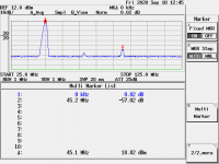
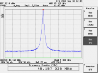
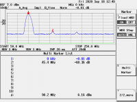
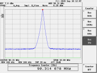
Since with the Timepod we cannot measure the phase noise at frequency upper to 30 MHz I attach the spectrum analysis of the frequency multiplier form 22 MHz to 45 and 90 MHz (series of 2).
Again there are no spurs and harmonics are very low.
With the doublers from 5 to 11 and 22 MHz we have demonstrated that the theory of the multiplication is valid in the real world, so you can figure out the phase noise of the 45 and 90 MHz devices simply adding 6 dB for each duplication to the base oscillator, in this case the 22 MHz one.
Attachments
I have never seen Potato offered anywhere but on Ebay. They don't
seem to play a role in the professional market.
And they play games with specs. I. e. specifying inverter delay
with less load than their own input, they could not drive themselves.
IIRC, it was about half a pF load, that would be just enough for my
Agilent 2.5GHz active probes.
Then I might be better off to use no gate at all.
Gerhard
I have reasons to believe Gerhard is right.
Their specs are, dubious - at best.
Their ebay account is inactive, & their US company address seems to be a residential house.
Even the name "Potato" should be enough warning for the diy enthusiast to approach with care.
WRT the name, sorry I forgot, anything with technical credibility should not have a humorous name... tell that to Elon. 🙂
WRT everything else above, this has all been discussed, I agree... but
you don't know till you measure. If I had a PN test set I'd measure a FF or INV just to satisfy my curiosity.
Nothing ventured....
TCD
It's very curious that now you trust the reliability of the Timepod measurements. It looks like the gear was allergic only to the ultimate devices.
BTW, even the 74AC04 sine to square converter seems to be non-existent below 100 Hz, only a little higher noise floor, so sorry but I have no time to design one more squarer.
As I said we are already devoloping another sine to square wave converter for the top version of our system, but it's could be called "RF style" since it uses discrete devices only.
I believe you are wrong, the simple gate sine to square converter does not add anything to the close in phase noise of the oscillator as you can see in the attached plot, 1/F and 1/f3 noise are superimposable.
As I said it adds noise floor and it's obvious since the gate operates as a non linear amplifier.
Moreover when a gate swithes there is a time when the channel is open, this time depends on the gate speed.
In this time the noise could cross the gate and show up at the output.
This could explain the noise floor while the close in noise is kept at low level, the same of the oscillator.
Slow edges do not have the time to cross the channel because the channel closes before they can cross it, while faster edges might cross it.
This could happen inside the 74AC04.
Thta's the reason why we are developing one more converter to achieve the better performance as possible along all the noise spectrum.
@andrea_mori
I could be wrong, but I think the increasing of the noise floor of AC04 was caused by the 30MHz narrow bandwidth of TimePod.
Timepod was designed for sine wave. So, may have limitation to measure square wave.
What's the rising/falling time of the square wave after your AC04? Can you post a phase noise plot without any suspension?
Regards,
Ian
I don't believe so, the Timepod has no problem to measure square wave output, please see post #2648, the same CMOS output oscillator measured by the manufacturer with the Aeroflex PN9000 vs Timepod measurement, the plots are almost superimposable.
And the measurement with a Agilent E5052B is the same.
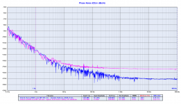
I attach the phase noise plot without spurs suppression (unuseful since you should use a ruler to better understand the phase noise behaviour), as you can see the plot is clean without appreciable spurious.
The increased noise floor comes from the CMOS gate, exactly the same issue you have with the flip-flop reclocker in your FifoPi. And maybe the same problem with the dividers inside the FPGA.
The high frequency noise of the gate modulates the phase noise while slow edges cannot cross the channel because it's faster to close.
The CMOS gate is a non linear amplifier, indeed the noise floor decrease a few dB powering it at 5V instead of 3V3 because at 5V it operates in a more linear region.
The reason we are developing a different sine to square converter using only discrete devices.
Anyway -150 dB noise floor is not bad for a simple pico gate, and mostly it does not add close in phase noise that's the most important region in digital to analog conversion.
And the measurement with a Agilent E5052B is the same.
I attach the phase noise plot without spurs suppression (unuseful since you should use a ruler to better understand the phase noise behaviour), as you can see the plot is clean without appreciable spurious.
The increased noise floor comes from the CMOS gate, exactly the same issue you have with the flip-flop reclocker in your FifoPi. And maybe the same problem with the dividers inside the FPGA.
The high frequency noise of the gate modulates the phase noise while slow edges cannot cross the channel because it's faster to close.
The CMOS gate is a non linear amplifier, indeed the noise floor decrease a few dB powering it at 5V instead of 3V3 because at 5V it operates in a more linear region.
The reason we are developing a different sine to square converter using only discrete devices.
Anyway -150 dB noise floor is not bad for a simple pico gate, and mostly it does not add close in phase noise that's the most important region in digital to analog conversion.
Attachments
Last edited:
Ian..
The Timepod had been used on many different occasions, to releive differences between different "square up" topologies.. Like the very neat measurement that I linked earlier, from KO4BB..
In that link You can find that indeed the noise floor is going down (the case with the HX2410), though it introduces deviations in the low frequency band..
And all that revealed with the same TimePod, using the same input filters (and Wilkinson splitters..) (so I do not trust..😀 😀)
@ andrea_mori
Basically a square wave contains both carrier frequency and odd-integer harmonic frequencies. For a 5.645MHz square wave, if AC04 has 1ns raising/falling time, it will also has frequencies of 16.935MHz, 28.225MHz, 39.515MHz.....and extended up to around 500MHz.
Parts of the high frequency harmonics will left within the Timepod passband, and most of them will be out of it's 30MHz input range. I understand Timepod can not measure anything above 30MHz. However can not see doesn't mean it's not exist. Anything equal or above Nyquist frequency will become aliasing noise that increases the noise floor of the result. That's why Timepod has pretty compromised measure result for square wave.
You can do a simple testing by using a high-pass filter cut the carrier frequency of your AC04 square wave output, and then see what's the result of your Timepod.
Or, you may have different point, then please explain how a Timepod using only 30MHz bandwidth to measure those high frequency harmonics of a square wave without affecting the result.
Regards,
Ian
Last edited:
Ian,
The Timepod samples at 77.76MHz, so Nyquist is ~39MHz.
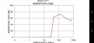
With respect to this, it does apply at each ADC channel input an antialiasing filter with the following insertion loss: (see table). It enters at 27MHz, and rises to 80dB almost, at below 100MHz. And is steep.
So, no aliasing effects in these measurements..
Ciao, George
The Timepod samples at 77.76MHz, so Nyquist is ~39MHz.
With respect to this, it does apply at each ADC channel input an antialiasing filter with the following insertion loss: (see table). It enters at 27MHz, and rises to 80dB almost, at below 100MHz. And is steep.
So, no aliasing effects in these measurements..
Ciao, George
Attachments
Last edited:
Furthermore, for an even better alias supression, one can apply further input filtering, as K04BB has done.
@ andrea_mori
Basically a square wave contains both carrier frequency and odd-integer harmonic frequencies. For a 5.645MHz square wave, if AC04 has 1ns raising/falling time, it will also has frequencies of 16.935MHz, 28.225MHz, 39.515MHz.....and extended up to around 500MHz.
Parts of the high frequency harmonics will left within the Timepod passband, and most of them will be out of it's 30MHz input range. I understand Timepod can not measure anything above 30MHz. However can not see doesn't mean it's not exist. Anything equal or above Nyquist frequency will become aliasing noise that increases the noise floor of the result. That's why Timepod has pretty compromised measure result for square wave.
You can do a simple testing by using a high-pass filter cut the carrier frequency of your AC04 square wave output, and then see what's the result of your Timepod.
Or, you may have different point, then please explain how a Timepod using only 30MHz bandwidth to measure those high frequency harmonics of a square wave without affecting the result.
Regards,
Ian
Again? It looks like you don't understand, the Timepod measures the phase noise, it's not a spectrum analyzer, and its limited bandwidth to 30 MHz is not an issue, it means that it cannot measure oscillators above 30 MHz, but it has no problem to measure square wave as long as the frequency does not exceed its limit.
I own a Lecroy Wavepro 954 and a spectrum analyzer (if you have seen the spectrum analysis of the frequency doubler), but I'm more interested in phase noise analysis when when dealing with master clock, and mostly in the close in phase noise since it's the region where oer brain is more sensitive to timing error.
Moreover 30 MHz for us is more than enough since our DACs operates at 5/6 MHz, all other devices have been designed for the audio community, we don't need high frequency master clock, and personally I don't even understand the purpose of such high frequencies.
So we have designed a small size board to fit you FIFO for those who want to use our oscillators, but it's not our way, we keep our devices away rather than stack them.
BTW, the 74AC04 sine to square converter we have designed is more than enough to be used with your FifoPi because, if I remember correctly, its noise floor is at least 20 dB better.
This does not mean that one cannot do better, indeed we are working on another squarer, but it will not be small size and cheap.
I think that Ivan hinted at the fact that if You feed an ADC with a signal above it's Nyquist limit, (and a square wave is a typical case for containing harmonics "into infrared.."..) - so if you would have un-treated residual harmonics from the clock under test hitting the ADC, then aliasing products will appear in your baseline spectra (mixing down), and loads of harmonics could maybe result even some noise floor modulation - - down to DC!
It do happen, not fantasy. For this the input filtering is paramount.
It do happen, not fantasy. For this the input filtering is paramount.
Ian,
The Timepod samples at 77.76MHz, so Nyquist is ~39MHz.
With respect to this, it does apply at each ADC channel input an antialiasing filter with the following insertion loss: (see table). It enters at 27MHz, and rises to 80dB almost, at below 100MHz. And is steep.
So, no aliasing effects in these measurements..
Ciao, George
Furthermore, for an even better alias supression, one can apply further input filtering, as K04BB has done.
Ciao, George[/QUOTE]
I think that Ian hinted at the fact that if You feed an ADC with a signal above it's Nyquist limit, (and a square wave is a typical case for containing harmonics "into infrared.."..) - so if you would have un-treated residual harmonics from the clock under test hitting the ADC, then aliasing products will appear in your baseline spectra (mixing down), and loads of harmonics could maybe result even some noise floor modulation - - down to DC!
It do happen, not fantasy. For this the input filtering is paramount.
Hi Ciao,
What you were discussing really makes sense. TimePod ADCs sample at 78MHz with SXLP-27 antialiasing filter cut-ff at 27MHz. That's what I suspected.
However around 60dB stopband insertion loss still means big amount of high frequency leakage for 16bit/80MHz ADCs. So all harmonics above 39MHz will lead to an increase of noise floor for sure.
Even more, I think the optimized frequency range of the square wave for Timepod would be 13.5MHz-30MHz based on this configuration (antialiasing filters behavior as square to sine wave converter ). But any square wave signal below 13.5MHz will lead to more harmonic frequencies falling into the SXLP-27 passband. The lower frequency square wave signal, the worse result.
It could be OK for normal square wave test, but for a ultra-low phase noise measurement, all of the above issues have to be taken into account. I don't think Timepod has a problem measuring sine wave from 0.5 to 30MHz. However, to measure phase noise of square wave (with a lot of high frequency harmonics), the result could be compromised or questionable unless better filters are applied.
Regards,
Ian
Attachments
Last edited:
The traditional phase noise measurement uses a double balanced mixer with one input driven to saturation. The Timepod emulates that in DSP essentially. Its important for phase noise to eliminate any amplitude content since that is not phase. However a gate will respond to noise as a time shift on its transition. Faster gates will be shifting their switching point less since they react faster to the rising/falling input yielding lest jitter/phase noise.
> Its important for phase noise to eliminate any amplitude content since that is not phase.
Phase and amplitude noise can be separated by taking the 90° / 0° components.
Phase and amplitude noise can be separated by taking the 90° / 0° components.
Which is equivalent to keeping the signals in quadrature, by the means of a PLL, in case of the classic mixer configuration. In that case the amplitude variations are not contributing to the mixer output noise.
From the timepod manual:
Input signals should be greater than 0 dBm for best
performance -- +5 to +15 dBm is recommended. The 5330A’s
specifications assume that sine-wave signals from 50 ohm
sources are applied to the INPUT and REF IN jacks, but you can
also measure CMOS and other square-wave clocks with the help
of a simple L-network (resistive or otherwise) to attenuate the
signal and increase the load impedance where necessary.1
Spur performance may be compromised with non-sinusoidal
inputs. This is especially true at lower frequencies where
multiple harmonics fall within the 0.5 – 30 MHz passband.
So a suitable low pass filter would be good to have.
The newer 53100A goes higher but for $$$.
Even more, I think the optimized frequency range of the square wave for Timepod would be 13.5MHz-30MHz based on this configuration (antialiasing filters behavior as square to sine wave converter ). But any square wave signal below 13.5MHz will lead to more harmonic frequencies falling into the SXLP-27 passband. The lower frequency square wave signal, the worse result.
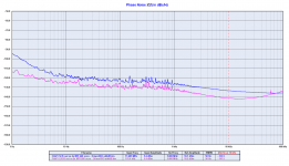
It looks like exactly the opposite, take a look at the attached plot.
The measured noise floor of a square wave at 176 KHz is 8 dB better than the measured square wave at 11 MHz, therefore just the opposite.
Even the first odd harmonic of the 11 MHz square wave (33 MHz) falls outside the SXLP-27 passband, while with the 176 KHz square wave there are a lot of odd harmonics falling in the SXLP-27 passband (528 KHz, 880 KHz, 1.232 MHz, 1.584 MHz, 1.936 MHz and so on).
So the measuremets show better noise floor at the lower frequency (176KHz), not at the higher frequency (11MHz).
Everyone can draw their own conclusions.
Attachments
Now this is only brainfarting, but
We have seen that the noise floor halves at each division by 2 of the carrier frequency.
From 11MHz to 176kHz there is an 62.5 division factor.
Let's round it to 64..
If the system would keep the physics all right, then it should show 2^6, that is -36dB difference in the floor, instead of 8dB.. and changing shape..
So there is something which is not perfect.
- Status
- Not open for further replies.
- Home
- Source & Line
- Digital Line Level
- The Well Tempered Master Clock - Building a low phase noise/jitter crystal oscillator