I do not understand this relentlessness on LDO.
All the issues attributed to LDO, IMO belong to every regulator that has loop gain pushed to the limit to achieve ultimate PSRR, Zout, Load regulation.
All the issues attributed to LDO, IMO belong to every regulator that has loop gain pushed to the limit to achieve ultimate PSRR, Zout, Load regulation.
I was wondering about that, as there's a thing about capacitive loading and stability in the LM431/TL431 datasheet as well.
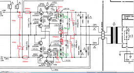
As this topic is Ginetto61 topic who was kind to send me a Nakamichi CA50 manual who's regulators happened to be very interesting for me i'll just show one that i finished today with some small modifications as i started with one design ,ended with another and didn't want to change the mods.I used Didden's idea for a green led refference biased with some j112 j-fet current sources of 2ma instead of the original Nakamichi 0.6v diode biased at 600ua , but i run te same bias current for the sziklai pair bias: 1.8ma by using a 1kohm emitter resistor which gives slighty higher noise, but better linearity for the current source biasing the sziklai pair.
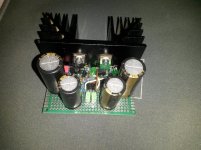
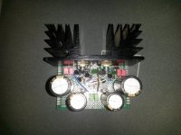
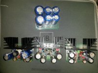
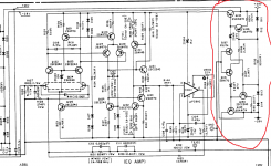
Thus i'm finishing a trio of voltage regulators,one +-30v,one +-20v andone +-10v that will be cascaded and supplied from a voltage quadrupler giving about +-43 v unloaded .The heatsinks aren't really needed as the multiplier can't hold those 40...43v for more than 200ma .
Thus i'm finishing a trio of voltage regulators,one +-30v,one +-20v andone +-10v that will be cascaded and supplied from a voltage quadrupler giving about +-43 v unloaded .The heatsinks aren't really needed as the multiplier can't hold those 40...43v for more than 200ma .
Attachments
Last edited:
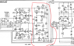
I think the R401 is only a start-up resistor.Replacing it by fets is useless.I used Didden's idea for a green led refference biased with some j112 j-fet current sources of 2ma instead of the original Nakamichi 0.6v diode biased at 600ua ,
Mona
I just wanted to make sure that the LED has a constant current through it but the base current of q403/407 needs to be noise free too as those transistors are providing the current to the output sziklai all the time.There's no feedback from the output and thus no start up ... just a continuous start up 🙂
Jan might like another arguably best phono preamps raw of regulators being supplied by that +-28v general regulator
Interesting from a technical view but I wonder what it does for the quality of the regulated output 🙂
Jan
I do not understand this relentlessness on LDO.
All the issues attributed to LDO, IMO belong to every regulator that has loop gain pushed to the limit to achieve ultimate PSRR, Zout, Load regulation.
+1
i have no idea...What's bugging me is that in the schematic i see virtually no capacitor at those regulator outputs while if you see a photo of the real thing , it has tons of big capacitors...Interesting from a technical view but I wonder what it does for the quality of the regulated output 🙂
Jan
The current through D409,410,411,412 (or LEDs) doesn't come from the R401 but via ZD402-Q408 for D409,410 and ZD401-Q404 for D411,412.That are the currents from the sources Q407,Q403 minus the base currents Q406,Q402.I just wanted to make sure that the LED has a constant current through it but the base current of q403/407 needs to be noise free too as those transistors are providing the current to the output sziklai all the time.There's no feedback from the output and thus no start up ... just a continuous start up 🙂
Mona
A 7815 can be used with a split winding transformer to provide both + and - regulated outputs and features wide band output Johnson noise of around 150uV RMS. If you use local filtering (22 Ohm and 100uF for example) around the opamps, the HF noise RTI of the opamp input is very very low - on a good opamp it will be pico Volts.
That leaves the LF noise. But there the opamp PSRR is very high, so you are still left with negligible noise RTI.
You can reduce line level ripple by putting a cap multiplier aka ripple eater in front of the regs. I am feeding in about 10 mV pk - pk into mine so the regulator line level ripple is single digit uV. The input ripple to the cap multiplier is about 500 mV pk to pk.
Yes, you are true about the original design...i just left the jfets there because i started with a different regulator in mind , switched to this one , then just thought that they can't harm as removing them is quite a problem due to this type of pcb i am working on , but i agree they are kind of useless due to q404/408. Now the start-up sequence is suspended due to continuous bias done by the j-fets.I might remove them later if i consider so.The green LED are actually in parallel with some 5v1 zeners as removing the zeners now from that pcb is a horrible task.The current through D409,410,411,412 (or LEDs) doesn't come from the R401 but via ZD402-Q408 for D409,410 and ZD401-Q404 for D411,412.That are the currents from the sources Q407,Q403 minus the base currents Q406,Q402.
Mona
Last edited:
For a super linear regulated PSU, I see two ways to go.
1) A cap multiplier in front of a regulator.
2) A regulator backed by a denoisier.
Are they other alternatives ?
How do these solutions compare ?
1) A cap multiplier in front of a regulator.
2) A regulator backed by a denoisier.
Are they other alternatives ?
How do these solutions compare ?
I never really needed super regulators...I only take the voltage regulation as a necessity sometimes as i don't want to fry some circuits that are supplied beyond 1/2 Vmax supply, but they are fun to build.
I have never had problems with 7805/12 etc in my designs.
They have always been more reliable than zeners.
Agreed, I don't know how many times I've repaired things that had a zener that, by design, was running hot and eventually failed.
In the end i needed to revert back to the original design as the fets weren't equal and the voltage multiplier couldn't hold the +-43 v under 250ma load, dropping to 31v leading the regulator to go down to +-26v instead of +-29.The current through D409,410,411,412 (or LEDs) doesn't come from the R401 but via ZD402-Q408 for D409,410 and ZD401-Q404 for D411,412.That are the currents from the sources Q407,Q403 minus the base currents Q406,Q402.
Mona
way (50...60mhz output transistors as unfortunately 80-90 MHZ- output transistors
Allow me to split some hairs. It is MHz. Mega = 10^6; m = 10^-3.
Herz is a person's name so must be capitalized. ;-)
Jan
Yes, I have to teach the younger ones at my company that the general rule (universal?) is that if the unit is named after a person, it is capitalized. Volt, Ampere, Watt, Hertz, Henry, Farad, Joule, etc. 'k' is lower case for kilo, 'K' upper case for Kelvin. I hv to get the model guys to stop using upper case K for resistors in LTspice in the macromodels.
final measurements: 29.2v into 150 ohm load with an input voltage from the quadrupler of +-34v which is good enough for me.I won't probably use more than 100ma in all the circuits i need to supply.In the end i needed to revert back to the original design as the fets weren't equal and the voltage multiplier couldn't hold the +-43 v under 250ma load, dropping to 31v leading the regulator to go down to +-26v instead of +-29.
Yes, I have to teach the younger ones at my company that the general rule (universal?) is that if the unit is named after a person, it is capitalized. Volt, Ampere, Watt, Hertz, Henry, Farad, Joule, etc. 'k' is lower case for kilo, 'K' upper case for Kelvin. I hv to get the model guys to stop using upper case K for resistors in LTspice in the macromodels.
Only the abbreviation (unit symbol) gets capitals, not the whole word. So the unit kelvin named after Lord Kelvin has unit symbol K, the unit volt named after Volta has unit symbol V and so on.
- Home
- Amplifiers
- Power Supplies
- Are you really fine with IC voltage regulators ?