Done.
Not sure if R17 in my schematic is even needed.
Sim works better without it.
If using 'normal' biasing with one transistor, R8 removal also slightly improves
sim results.
I just realized that relatively early clipping in my tests (at 62 Vpp) might be due to
my lab PSU running out of steam (amps).. Will re-test with real (linear) PSU later on.
Last edited:

A beauty!
Russia still makes these metal-can op-amps, or it's a old stock?
I remember these big, waxed paper (?) capacitors from 70s, I guess they are back in fashion 🙂
Russia still makes these metal-can op-amps, or it's a old stock?
I remember these big, waxed paper (?) capacitors from 70s, I guess they are back in fashion 🙂
Something produces, something from stocks. I like operational amplifiers and transistors in metal. Now on K153UD2 (LM101A) I do the device
These are 0.15 Ohm C5-16 resistorsI remember these big, waxed papers (?)
Last edited:
No, this is an old completed project. But I'm already doing something new.So this is the new version, not finished yet?
Last edited:
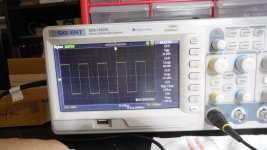
When I add a diode (1n4148) between B-C of Q1 (clip control), the rise time on square waves goes from 2.4us to 3.2us. This affects slew rate.
Not sure if it's worth it...
Not sure if it's worth it...
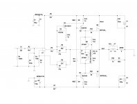
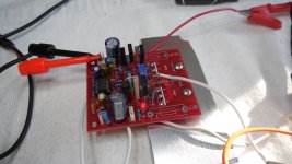
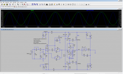
Also, since I have PCBs left, I tried a simplified hexFET version of this amp.
'Normal' biasing has been used, with Si transistors with low beta
(ZTX, but also two MJE 340 can be used). Attached schematic is 'as-built'.
Even though it's much simplier (no drivers), it simulates in spice better than BJT version.
I quickly built it last night, using junk parts salvaged from the past, failed projects, and it seems to work just fine.
All test with 40V rails, 8 Ohm resistive load, and idle current set to approx 50mA for each of the output devices.
It's actually on this FET version I discovered that D3 slows rise time, so it's left as optional in the schematic.
Attachments
-
 radio_1987_09_hexfet_tiny.jpg277.1 KB · Views: 626
 -
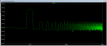 ru_fet_fft.png16.6 KB · Views: 645
 -
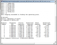 ru_fet_thd.png25.6 KB · Views: 573
 -
radio_1987_09_hexfet_tiny.asc9.3 KB · Views: 103
-
 DSCN0254.JPG264.3 KB · Views: 137
 -
 DSCN0250.JPG271.2 KB · Views: 149
 -
 DSCN0242.JPG260.6 KB · Views: 148
 -
 DSCN0241.JPG253.8 KB · Views: 149
 -
 DSCN0237.JPG266.9 KB · Views: 172
 -
 DSCN0235.JPG240.3 KB · Views: 610
Last edited:
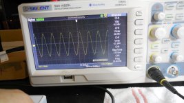
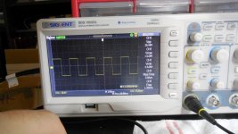
While at it, I also tried 2 other kinds of JFET op-amps (vs. TL071 tried first) :
1) LF356
2) LT1056
All look the same, including slew rate (so the op-amp is NOT the limiting factor)
With LT1056, I see some small oscillations in the bottom edge of the sinus,
but only when Vpp is approaching over 60V.
1) LF356
2) LT1056
All look the same, including slew rate (so the op-amp is NOT the limiting factor)
With LT1056, I see some small oscillations in the bottom edge of the sinus,
but only when Vpp is approaching over 60V.
On the BJT version, tried to fiddle with feedback loop capacitors C6/C7 (both at 47pF), but it looks like the sim was right - 47pF is the minimal value to get
perfect square waves. So I guess they will stay at 47pF.
perfect square waves. So I guess they will stay at 47pF.
LT spice
I tried the other op-amps in the real build, not in the sim. I tried what I had 🙂
I tried the other op-amps in the real build, not in the sim. I tried what I had 🙂
Last edited:
LT spice
I tried the other op-amps in the real build, not in the sim. I tried what I had 🙂
I work at MS-12.
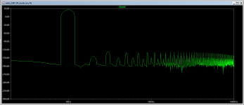
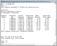
Tweaked few component values for the hexFet version, Thd is significantly lower..
I guess it won't hurt. Will try this is in my build tomorrow.
In the sim, these changes also improve BJT version..
I guess it won't hurt. Will try this is in my build tomorrow.
In the sim, these changes also improve BJT version..
Attachments
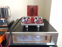
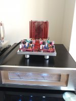
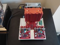
BJT (original) version of the amp is mounted on the chassis, connected to PSU (big box below, with VU meters)
and playing music.
So far so good. Music sounds great, chassis is cool,
driver's temperature is fine (53 C), so these small heatsinks are adequate.
DC offset is minimal (2-3 mV), amp is perfectly stable.
Still running with 100mA idle current for output devices.
As far as Alu chassis goes, this is the smallest one I built so far (15 x 14 cm), with only one fan (Noctua).
From past experiences it should be enough.
Attachments
Last edited:
- Home
- Amplifiers
- Solid State
- Unusual amp from 1987