Hi Meanie,
Nice work! I recall you were running linear trafo and SLBs prior the SMPS. Was the residual EMI from the trafo still getting hum onto the Edcor? I recall mu-metal was needed in my case to reduce it.
I had a thread about the noise on M2 and when I tried two 24v 5A SMPS bricks in series, the hum (and forest of noise) went away. It was the proximity of the Edcor to the power trafo all the time. I convinced myself by moving the trafo outside of the chassis and the hum went away. That’s the only thing with signal transformers - prone to EMI noise pickup.
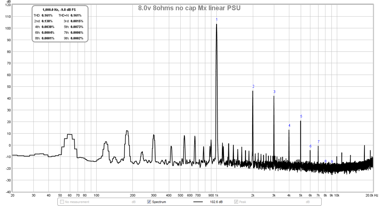
Here was FFT with linear trafo PSU:
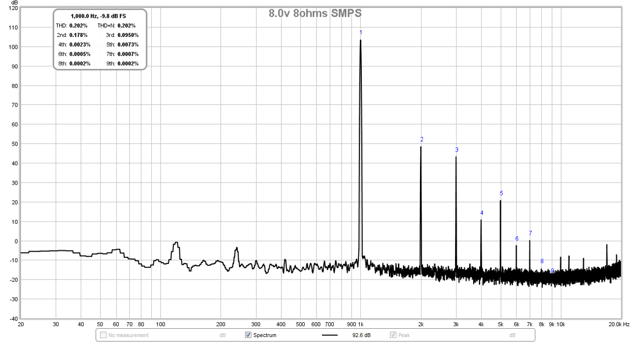
With SMPS:
Great that the Cresnet ones you have don’t hiccup due to large in rush turn on transient. Glad to see Melbournes are tough enough to take the +/-28v. I run them up to +/-32v sometimes when I need a lot of swing.
Nice work! I recall you were running linear trafo and SLBs prior the SMPS. Was the residual EMI from the trafo still getting hum onto the Edcor? I recall mu-metal was needed in my case to reduce it.
I had a thread about the noise on M2 and when I tried two 24v 5A SMPS bricks in series, the hum (and forest of noise) went away. It was the proximity of the Edcor to the power trafo all the time. I convinced myself by moving the trafo outside of the chassis and the hum went away. That’s the only thing with signal transformers - prone to EMI noise pickup.
Here was FFT with linear trafo PSU:
With SMPS:
Great that the Cresnet ones you have don’t hiccup due to large in rush turn on transient. Glad to see Melbournes are tough enough to take the +/-28v. I run them up to +/-32v sometimes when I need a lot of swing.
Last edited:
@Audiobear, i am not sure if those listed in his site is the actual one i have. I contacted him directly before ordering. According to him, this current one i have is an older model, the newer ones are +/-24Vdc, with some variations depending on your local supply voltage. You may want to contact Sami for more infos.
@Xrk
The twin SLB initially setup was meant for my M2X, but i struggled to get it down to a reasonable hum level, it wasn't ground looping issues, more of a induced emi from the main trafos to the Edcor directly. Mumetal is the alternative solution, but it is something i do not have on hand. So the M2X project was shelved and make way for the USSA5, which were happily powered by the twin SLBs!
M2X is a very nice power amp to have, hum pickup remains an issue, moving main linear ps trafos away or into another separate chassis is preferred, using Mumetal helps too, using smps is another method to rectify the hum problem.
Will run a REW FFT on my M2X when i got time...
Hi. I also posted that in the PSU guide thread, but nobody comented yet there. Perhaps someone will be nice to give a word here?
I read half of the PSU guide thread to prepare for the PSU build for my M2X, and I think I am ready to make my choices.
Though I have one question about the Inrush Current Limiter (ICL). NP is using just one CL-60 on the 230V supply schematic for that, but the honourable AndrewT was commenting several times that it's not enough, and at least 2 CL-60 should be used in series on 230V live line, but something of 60-80 ohms "cold" resistance would be preferable (2 CL-60 have about 22 ohms).
I found this ICL that I would like to use (75 ohms), but could some experts comment if that is ok, or are there some reasons that I do not know that makes this choice unsuitable for his application.
MS22 75004
My other choices are as below. I tried to be concervative as I am more of the "enough is enough" type than "more of good is better". Again, if someone would care to comment, I would appreatiate it very much (this is my first sourcing of the parts):
300VA 230V-2x18V Toroidy transformer;
Monolithic bridge rectifiers 200V 35A (saves space on my 4U/300 chassis, easier and cheaper);
No optional PI resistors (8 in total);
No input nor output snubbers (no need for class A amplifier);
18000uF 50V capacitors (we all want to be a tiny bit smarter than Papa, don't we?);
2.4k bleeder resistor;
3300pF line X1 rated capacitor and ICL (as above);
CL-60 on the audio ground to "float" it.
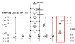
And another small question: if I want to have 2 blue LEDs on the front pannel, where is the best place to wire them from? I would want to keep PSU LEDs as they are, as I consider them being a safety warnings. As I will not be using the output snubber, could I put the pannel LED resistors in the place of R11, R12 and wire LEDs in place of the capacitors C17, C18? That would look neat, but wouldn't it do any bad to the power supply?
Thanks to everyone who will be kind to comment!
I read half of the PSU guide thread to prepare for the PSU build for my M2X, and I think I am ready to make my choices.
Though I have one question about the Inrush Current Limiter (ICL). NP is using just one CL-60 on the 230V supply schematic for that, but the honourable AndrewT was commenting several times that it's not enough, and at least 2 CL-60 should be used in series on 230V live line, but something of 60-80 ohms "cold" resistance would be preferable (2 CL-60 have about 22 ohms).
I found this ICL that I would like to use (75 ohms), but could some experts comment if that is ok, or are there some reasons that I do not know that makes this choice unsuitable for his application.
MS22 75004
My other choices are as below. I tried to be concervative as I am more of the "enough is enough" type than "more of good is better". Again, if someone would care to comment, I would appreatiate it very much (this is my first sourcing of the parts):
300VA 230V-2x18V Toroidy transformer;
Monolithic bridge rectifiers 200V 35A (saves space on my 4U/300 chassis, easier and cheaper);
No optional PI resistors (8 in total);
No input nor output snubbers (no need for class A amplifier);
18000uF 50V capacitors (we all want to be a tiny bit smarter than Papa, don't we?);
2.4k bleeder resistor;
3300pF line X1 rated capacitor and ICL (as above);
CL-60 on the audio ground to "float" it.
And another small question: if I want to have 2 blue LEDs on the front pannel, where is the best place to wire them from? I would want to keep PSU LEDs as they are, as I consider them being a safety warnings. As I will not be using the output snubber, could I put the pannel LED resistors in the place of R11, R12 and wire LEDs in place of the capacitors C17, C18? That would look neat, but wouldn't it do any bad to the power supply?
Thanks to everyone who will be kind to comment!
I have been using one CL-60 on 230V mains for all my builds so far.
Works for me on 500VA transfomer as well as just one CL-60 for dual mono (2x 400VA transformers). I believe I am using 1.25 A to 1.6A mains fuse.
One interesting fact though - the sand-filled ceramic-body mains fuses are more prone to blowing at start-up than the glass-body fuses of the same rating. Have switched to all glass-body fuses again to keep them closely rated to the steady-state current draw.
Best regards,
Claas
Thanks for sharing, Claas. As you know from practice what fuses are better, then I conclude that you do blow a fuse or another on power up from time to time. Is that correct? How offer does that happen to you? I think if ICL is chosen correctly, that would never happen?
-Alvis
-Alvis
I always start with a rather low-rated fuse. Say, 1A when the steady-state current draw is 0.7A. If it blows, I go for the next bigger one. Since fuses are cheap, I have a few boxes of 10 for most of the ratings.
I think if the fuse blows at power-on or not, if you're really close-rated, depends where on the curve of the mains voltage (regarding the phase) you throw the switch. So, if in some cases, a fuse blows every few days, then I go for the next higher value (say, from 1.25A to 1.6A). If it blows only once a month or so, or even more rarely, I stay with the value.
I did notice with the ceramic fuses that they are more prone to blowing at the same amperage rating as the glass ones. I don't really know why that is. I had tried them because I followed the folklore that they should be better sounding because of the damping of the wire by the sand filling.
I look at the system more from the viewpoint of choosing the correct fuse value instead of choosing an ICL that provides a maximally damped inrush.
I want some inrush damping from an ICL. But for me, using a CL-60 or similar, I also look at the steady-state resistance once it's heated up. I want that to be as low as possible, in order to not raise the impedance of my power supply too much by using the NTC.
So, an NTC used as inrush current limiter should provide some inrush damping at start-up, but have as low an on-resistance as possible. That implies also that it needs to get hot in use, really hot ... 😛
Of course, a rely-based solution would provide all of that, but at higher complexity.
You can't beat the simplicity of a well-tuned combination of NTC and mains fuse ... 😀
Best regards, Claas
Speaking of hot NTCs...
I learned the hard way while testing. Ensure a bit of time to allow the NTC(s) to cool after powering down before powering up again. It may be overkill, but I allow about a minute.
If you don't, that's almost a sure way to blow a closely / properly rated fuse. It's mentioned in several threads, but it can't hurt to repeat.
Maybe one or the other of these threads might be useful
Not thrilled with CL-60 inrush limiter in USA/160W Class A First Watt designs
PCB: low voltage On-Off switch drives AC mains relay \ includes soft start .. H9KPXG
Not thrilled with CL-60 inrush limiter in USA/160W Class A First Watt designs
PCB: low voltage On-Off switch drives AC mains relay \ includes soft start .. H9KPXG
Have you tried all the daughter cards with the 27v PSU?
Sorry Bones13, I totally missed your post till just now. I have only had the Norwood board installed using the 27V PSU.
Have you ordered a transformer?
You can also use CL60’s in conjunction with a delayed SSR (solid state relay) as a soft start. That gives you back some voltage headroom without the drop caused by the hot NTC. Also, the NTC is only used for a few seconds to limit the in rush to charge the field of the trafo and bulk caps so doesn’t get or stay hot. Several designs are available on DIYA - check the GB Forum.
Yes, I ordered from Toroidy (300VA 20v secondary). Couple weeks to build, then whatever shipping time from Poland to USA happens. I’m hoping to see them mid September.
Finished my H9KPXG boards. SLB boards this weekend. I’ll need to Quasi the transformers when they get here to finish snubbers on the SLBs.
I need to order black front plates for the amps to change out when I take everything apart. Found some black momentary switches on a PC customization site.
Enjoying this rebuild process. Thanks again to @MarkJohnson and @XRK971 for all your contributions.
Maybe one or the other of these threads might be useful
Not thrilled with CL-60 inrush limiter in USA/160W Class A First Watt designs
PCB: low voltage On-Off switch drives AC mains relay \ includes soft start .. H9KPXG
Thank you for the links, Mark. That was really usufull. And I also did some additional read up on ICL on the Ametherm site. One thing I am sure - the CL-60 is definitely not the optimal choice (especialy on 230V), using 2 of them is a bit better, but a right way it seams to me is using one properly selected ICL.
From what I read, I reckon this:
1.- the stable state curent (SSI) of M2X on 230V should be 160W / 210V = 0.75A (or a bit less)
2.- you do not want your ICL to run much below the rated SSI as then it would not get hot enough and the resistance would be sub-optimal
3.- so, rating of 1.1A of SSI (or 2A for bigger margin) is what you want for 230V
So, my choice as of now is either SL10 50001 (1.1A rated) or SL10 50002 (2A rated). Both are 50 ohms and should limit the inrush current to about 4A as I understand it (way below the 10A that a 1.25A slow-blow fuse should withstand for a short inrush).
Either I got it right from what I read, or I will learn it the hard way later 😉
Going with some active ICL circuit is definitely a good idea also. But I will let it wait for the next project.
-Alvis
Last edited:
And what about my idea for the front panel LEDs? Is is a good idea to wire them in the place of the output snubber resistor and capasitor (that I will not be using). Or would that spoil the PSU current somehow?
And another small question: if I want to have 2 blue LEDs on the front pannel, where is the best place to wire them from? I would want to keep PSU LEDs as they are, as I consider them being a safety warnings. As I will not be using the output snubber, could I put the pannel LED resistors in the place of R11, R12 and wire LEDs in place of the capacitors C17, C18? That would look neat, but wouldn't it do any bad to the power supply?
You can take power right from the VPos output of your PSU boards. You will need a significant resistor inline with the LED. I typically use 150K.
Why is it different from the LED included in the PSU circuit? BOM recommends 4.7-10K resistor. I think if I put it on the PCB instead of the snubbing capacitor it will get the same 24V as the power indicator LED, so it require the same resistor that I can put in the place of the snubbing resitor on the PCB. What don't I understand here, where's my error?
The 4.7k-10k recommendation is based on “normal” LEDs. Almost all LED in the last few years are very, very bright compared to LEDs made over the last few decades. Where an older inexpensive LED needed 2-5mA to light up brightly, a new LED might only need only 100-200uA, particularly when viewed on-axis.
Regardless, try it with what you have, if too bright make the resistor bigger, and vice-versa if too dim.
Regardless, try it with what you have, if too bright make the resistor bigger, and vice-versa if too dim.
You can take power right from the VPos output of your PSU boards. You will need a significant resistor inline with the LED. I typically use 150K.
duh - 15K...
OK, 15K makes sense 🙂 Overall, I think it's not so difficult to estimate the brightness if you have a datasheet of the LED you are going to use. I can do it, no problem.
But in general, I am a total newbie in electronics, so I would be happy if anyone could comment about my idea of wiring place of these front pannel diodes, as I really do not know if it's totaly fine to stick the diode and the resistor anywhere between the V+ or V- rail and the ground (observing the correct polarity, of course, anode getting "more possitive" side).
So, again, as I will not be using the output snubber, I will have a nice places left on the PCB that looks quite "ingenious" for me to be used for these diodes (R12, C17). OK?
Attachments
- Home
- Amplifiers
- Pass Labs
- The diyAudio First Watt M2x