Which is a pity. Forums like stackexchange.com DO NOT tolerate NON-TECHNICAL opinionated posts. They even go the extent of closing questions which they deem provoke suck replies.
I find opinions allow one to average the general consensus, then dig deeper..... sometimes aligning with your own observations sometimes not.
in the end leaving one further educated (like it or not!)
It’s a learning process for some......no need for censorship. 😛
simple is always good, easier to debug.
i sometimes see 20+ transistors in an amp when 10 will do the job ok.
i sometimes see 20+ transistors in an amp when 10 will do the job ok.
I find opinions allow one to average the general consensus, then dig deeper..... sometimes aligning with your own observations sometimes not.
in the end leaving one further educated (like it or not!)
It’s a learning process for some......no need for censorship. 😛
Hi ! thanks a lot. Actually i chose The Longue for a reason.
Even if minimal audio design is starting to become a religion for me 😱
Seriously ... i understand it is so difficult to optimize a simple design. I cannot image how challenging must be to optimize a complex one 😱
@ginetto61
i'll leave others better than me to guide you thorugh the audio realm 🙂

simple is always good, easier to debug.
i sometimes see 20+ transistors in an amp when 10 will do the job ok.
Yes that is my question. Or better i am very willing to accept the superiority of a more complex design if someone shows me some kind of instrumental evidence. Like lower distortion, better PSRR and so on.
But if a simpler design provides already great results ...
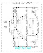
I am very interested in low open loop gain discrete op-amps and always looking for some comparisons between different designs.
One of the first i guess was the preamp module in the Mark Levinson JC2 line preamp ?
I had a great admiration for that preamp ... then i saw on Youtube a video were the original module was replaced by an op-amp ... for better performance 🙁
For sure the original module was more a minimalist design (see the video below at 2:02)
VTA TV Review Mark Levinson jc-2 preamplifier - YouTube
Attachments
Last edited:
yes ...you have this option today where an op-amp can be even better than 100 transistor circuit of the old days...but that doesn't work everywhere.
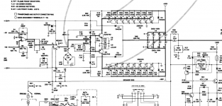
To replace 513 with 519 and 515 with 517.
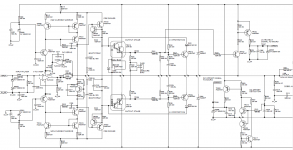
Actually I think you want to leave out Q517-519 and have the signal output from Q513-515 ommitting the end-follower stage. Initially I thought you wanted to connect Q517-519 to Q501-505 directly. That won't work.
Apart from the bias components (D509, R523, C505), the signal is there already (midpoint of Q513-515) indeed and can be used by an high impedance load (*). If the feedback network is connected from there, the load is some 21k and will have impact on the open loop gain. Any other load will change this too and that is the reason to add an output buffer (Q517-519) - it is a commercial amp so reliability is important.
Further simplification without to much degredation can be done by replacing the current sources (Q511-509) with resistors. Also the differential can be replaced by singel transistors - a different stabilisation and biasing is needed however. The small FET-input Hiraga is such a design. Ultimately you can use one transistor for the amplification as an example of minimal engineering.
(*): If there was a transistor (or any other device) with a low output impedance on its collector (or drain or whatever), the 'classic' output stage becomes unneccessary. With tubes this is a triode, with semi's this is a SIT (see the Pass section on this platform). Alas single polarity ('N-channel') only.
Unless...
he won't get anywhere changing the rotel structure unless he's building another amplifier out of it...he could simply use an op-amp replacing the whole structure and that would be much safer.
Actually I think you want to leave out Q517-519 and have the signal output from Q513-515 ommitting the end-follower stage. Initially I thought you wanted to connect Q517-519 to Q501-505 directly. That won't work.
Hi ! yes i see two options.
- Using Q513-515 as output stage and adjusting the circuit accordingly.
- To put 519 at the place of the 513 and the 517 in place of 515.
thanks a lot. So the original schematic is more reliable and maybe even better performing in terms of distortion and driving ability. No more questions then. I will keep my ravings inside my mind. 😱Apart from the bias components (D509, R523, C505), the signal is there already (midpoint of Q513-515) indeed and can be used by an high impedance load (*).
If the feedback network is connected from there, the load is some 21k and will have impact on the open loop gain. Any other load will change this too and that is the reason to add an output buffer (Q517-519) - it is a commercial amp so reliability is important.
this was another doubt of mine. So you say that using simple resistors will not have a sensible negative impact on performance ? good !Further simplification without to much degredation can be done by replacing the current sources (Q511-509) with resistors.
I have another schematic of an older p303 here ( i guess it was TOTL in the onkyo line during the late seventies ?)
they used resistors and +/-33VDC voltage rails
thanks a lot. Which design do you prefer for the differential stage ?Also the differential can be replaced by singel transistors - a different stabilisation and biasing is needed however.
The small FET-input Hiraga is such a design.
actually i would be curious to do that but i do not know how to connect the output pair to that single transistor working in its optimal conditions of courseUltimately you can use one transistor for the amplification as an example of minimal engineering.
Could it be that a highly optimized (i.e. careful biasing, parts selection, etc.) 3 bjts line stage surpasses more complex discrete op-amp stage ? 🙄
😱 i start to be excited 😱
this is more ... difficult(*): If there was a transistor (or any other device) with a low output impedance on its collector (or drain or whatever), the 'classic' output stage becomes unneccessary. With tubes this is a triode, with semi's this is a SIT (see the Pass section on this platform).
Alas single polarity ('N-channel') only. Unless ...
But i like the 3 bjts line stage idea a lot indeed ...
Attachments
you might be interested in SAE 3100 Lender vas circuit...
SAE 3100 Power Amplifier Technical Review & Repair – AmpsLab
SAE 3100 Power Amplifier Technical Review & Repair – AmpsLab
As said, the small FET-input Hiraga.Which design do you prefer for the differential stage ?
That needs some calculations....how to connect the output pair to that single transistor...
I understand. The idea and proof of concept was almost instantanious, but it took me some years to get all the calculations right (partially below). Now I can design your wanted two-stage design without output buffer with low output impedance (and no feedback), completely symmetrical....this is more ... difficult ...
I spent a lot of time with Op-amps in my youth. 🙂
Marvellous things if you didn't expect a lot of power from them. The NE 5534 and TL-074 were just superb as pre-amps.
But try and get them to drive a pair of loudspeakers and you ran into all sorts of problems.
Mostly feedback stability.
Marvellous things if you didn't expect a lot of power from them. The NE 5534 and TL-074 were just superb as pre-amps.
But try and get them to drive a pair of loudspeakers and you ran into all sorts of problems.
Mostly feedback stability.
Attachments
This is no surprise. Look into the internal circuitry, often you will find 2 or 3 voltage amplifying stages that you cannot compensate externally. This makes op-amps in-attractive as error amps in closed loop power amps.I spent a lot of time with Op-amps in my youth. 🙂
Marvellous things if you didn't expect a lot of power from them. The NE 5534 and TL-074 were just superb as pre-amps.
But try and get them to drive a pair of loudspeakers and you ran into all sorts of problems.
Mostly feedback stability.
TL071, did you mean?I spent a lot of time with Op-amps in my youth. 🙂
Marvellous things if you didn't expect a lot of power from them. The NE 5534 and TL-074 were just superb as pre-amps.
NE5534 was used in many (all?) audio mixing consoles. Audio signal passed through dozens of these op-amps, and still great recordings were produced.
Not too sure, my friend. This was 40 years ago.
Of course I remember mixing consoles with many NE 5534 units. And many noisy pots.
IIRC, the TLO71 was the single op-amp package. TLO72 was a dual. TLO74 was a quad.
There was also the TLO84.
But, IMO, if you'd seen one op-amp, you'd seen them all. 😀
Of course I remember mixing consoles with many NE 5534 units. And many noisy pots.
IIRC, the TLO71 was the single op-amp package. TLO72 was a dual. TLO74 was a quad.
There was also the TLO84.
But, IMO, if you'd seen one op-amp, you'd seen them all. 😀
i think it all depends on who's in charge with the design...But try and get them to drive a pair of loudspeakers and you ran into all sorts of problems.
Mostly feedback stability.
Attachments
Aw, you've set me off. 🙂
The best recording of a live concert ever made:
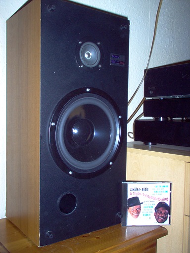
Count Basie and Frankie. Cut direct from twin microphones to LP disk. Not a single op-amp involved. That my friend is Engineering. Never overloaded either. Brilliance.
The best recording of a live concert ever made:
Count Basie and Frankie. Cut direct from twin microphones to LP disk. Not a single op-amp involved. That my friend is Engineering. Never overloaded either. Brilliance.
you might be interested in SAE 3100 Lender vas circuit... SAE 3100 Power Amplifier Technical Review & Repair – AmpsLab
Thanks for the link. I like this amp a lot. My power need stops at about 40-50W/channel and this one would be splendid. Unfortuately very rare here in Italy. American audiophiles are very very lucky ... there is a sea of great opportunities in hifi
I understand that some parts age worse than others. An old amp restoration is a nice way to start doing something. Next step could be to try to repair something.
As said, the small FET-input Hiraga.
That needs some calculations.
I see. My idea is to start simulating something very basic. And stay basic.I understand. The idea and proof of concept was almost instantanious, but it took me some years to get all the calculations right (partially below). Now I can design your wanted two-stage design without output buffer with low output impedance (and no feedback), completely symmetrical.
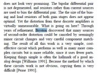
I am attaching an extract of a review about my Bryston preamp that i found very intriguing. I wonder if designers are more stimulated by a more complex design or by the optimization of a more basic one. I like simple designs. They look very elegant to me.
Attachments
Aw, you've set me off. 🙂
The best recording of a live concert ever made: Count Basie and Frankie.
Hi ! thanks a lot for the valuable suggestion. I will look for it I am always looking for great recordings for both music pleasure and testing
Not easy to have both
ok but there must have been something between the mics and the LP. Like a preamp i guess ? 🙄Cut direct from twin microphones to LP disk. Not a single op-amp involved. That my friend is Engineering. Never overloaded either. Brilliance.
- Home
- Member Areas
- The Lounge
- Overengineering in audio equipment