Here is where I am talking about. Its like its overdamped approaching the flat top and underdamped coming off of the flat top.
I would saturate a sine wave and sweep frequency to investigate.
You are looking at different parts of the square wave, the leading vs
trailing edge. a linear RC time constant has this character.
Still, we would not be surprised by a subtle difference leading-to-leading
or trailing-to trailing comparison for any circuit that is not perfectly
symmetric.
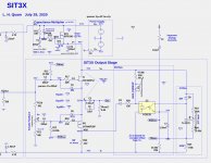
After bench testing and simulation I found several improvements to the SIT3X output stage, mostly involving the bias circuit. They involve the power up/down behavior and the opto circuit behavior at higher power levels.
The SIT sound appears to be best when the M1 PFET is operating near the point of being a current source, and thereby its drain current is the best indication of the overall bias current and the J1 opto coupler has now been eliminated. The result is that now the bias current changes very little between 1W and 25W output.
Here is the revised OS:
Attachments
'The SIT sound appears to be best when the M1 PFET is operating near the point of being a current source'
What did you find the optimum percentage of Schade feedback to be?
Would you lose much performance if it was 0% (100% CC)?
What did you find the optimum percentage of Schade feedback to be?
Would you lose much performance if it was 0% (100% CC)?
'The SIT sound appears to be best when the M1 PFET is operating near the point of being a current source'
What did you find the optimum percentage of Schade feedback to be?
Would you lose much performance if it was 0% (100% CC)?
I am not sure what you mean by 0% (100% CC). With no Schade feedback, phase of the current from the SIT is inverted and the output power is greatly limited because the SIT current partially cancels path of the from the PFET. The value for the Schade feedback where the SIT acts as a constant current source and at smaller value for the feedback, the SIT current phase is inverted and "fights" against the current from the PFET.
I will be showing some FET AC current curves at a variety of power levels and Schade feedback levels.
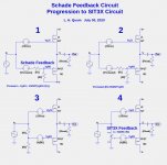
Circuit 1 shows Schade feedback in a common drain (source follower) output stage. FET gate voltages VgJ1 and VgM1 are required to obtain the desired operating point, assuming the average of the input signal is zero volts. The bias voltage into the left end of R1 must be adjusted to VSchade1+VgM1+R1/R2*(VgM1-V(V-)) to compensate for the voltage shift due to the DC current thru resistor R2.
In circuit 2, the bottom end of R2 is connected to ground, changing the the bias generator voltage to VSchade2=(R1+R2)/R2*VgM1.
In circuit 3, the feedback voltage divider is moved to the left side of the bias voltage generator, and the bias voltage becomes simply VgsM1.
In circuit 4, the voltage divider is replaced by a pot, which is adjusted to the value A=R2/(R1+R2).
Attachments
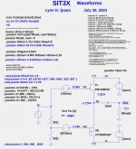
Shown below and in the attachment is a simplified, selef contained simulation of the SIT3X output stage, whose waveforms will be shown in the following posts. The generated .log file will show the fourier results and the values of various parameters and signal measurements.
Attachments
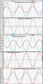
The plots below show the Watts=1, Rload=8, and 5 different values of the A parameter.
From top to bottom:
From top to bottom:
- A=.830 strong FET current cancellation
- A=.877 M1 approximates a CCS
- A=.896 H2 is minimized
- A=.932 J1 approximates a CCS
- A=.987 strong FET current cancellation
Attachments
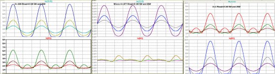
Each plot below shows the J1 and M1 FET current waveforms at 1 Watt, 5Watts, 25 Watts, into an 8R load.
From left to right:
In a future series of posts show relationship to SIT-1, SIT-2, and SIT-3(?).
From left to right:
- A=.830 Ix(J1d) clips and leaves class-A at around 10 Watts
- A=.877 M1ccs Is(M1) is well behaved, but contributes to output at high power levels
- A=1.00 Is(M1) clips and leaves class-A at less than 5W
In a future series of posts show relationship to SIT-1, SIT-2, and SIT-3(?).
Attachments

Very clear and comprehensive analysis as always. I applaud your patience at documenting and publishing everything. Thank you!
One question regarding the latest exposition which I suspect itsmee was also trying to ask - how different is the behaviour of this output stage (A=0.877) with a more standard single ended SIT based one, i.e. with the PFET configured as a pure current source with no signal input? You mention that that the PFET contributes a little at high outputs in the SIT-3X OS but how significant is this practice? I'm just curious.
One question regarding the latest exposition which I suspect itsmee was also trying to ask - how different is the behaviour of this output stage (A=0.877) with a more standard single ended SIT based one, i.e. with the PFET configured as a pure current source with no signal input? You mention that that the PFET contributes a little at high outputs in the SIT-3X OS but how significant is this practice? I'm just curious.
As I mentioned at the end post #288, I will be comparing the behavior of the SIT3X to the FirstWatt SIT-1, SIT-2 and perhaps the SIT-3. As a preview, here are some differences:
- SIT-1 is a single-ended, common-source output stage.
- SIT-2 is a mu-follower, common-source output stage, with the mu-follower adjusted to operate either at or very near being a constant current source (CCS). Both FETs have degeneration.
- SIT-3 is a push-pull, common-drain output stage, with the right amount of degeneration of the PFET to obtain CCS behavior of the PFET. A transformer is used as the front-end gain stage.
- SIT3X is a higher power, push-pull, common-drain output stage, with no degeneration the the output FETs which can be adjusted as being a CCS. Because the SIT is a higher power Tokin 2SK182ES presenting a high capacitance load to the front-end, and a higher output voltage swing is required from the front-end, a separate low-output impedance front end is required.
well , differences are different for different ears 
what I know - they are all sounding good, different enough to justify their existence as different amps
of course, horses for courses, though I'm blessed to have speakers happy with any of those
one thing is sure - SIT-1 ( which I must make one day, being obliged) and Singing Bush (also being obliged) will be strictly winter amps, while I'm thinking to make special one for Summer, 2W and - what's that - 10W of dissipation?
either with SJEP170R550 or maybe Ge amp, same heat bracket
enough off topic, please continue 🙂
differences in how these amplifiers actually sound
I admire the length of work and research made, thanks for sharing.
Not that I was lost following your math equations, but I would really be looking into how you could describe in simple words how each SIT sounds to your ears.
I'm sure there are others who also have the same interest, but did not have the chance to hear all SIT variant.
[*]SIT-3 is a push-pull, common-drain output
stage, with the right amount of degeneration of the PFET to obtain CCS
behavior of the PFET. A transformer is used as the front-end gain stage.
As no one except ZM has been provided with actual SIT-3 schematic, it is
understandable that this statement is in error. The Pfet is not a CCS.
Apart from that, your exposition is masterful.


I have never been able in simulations to obtain CCS behavior in the SIT-3 topology, but it is easy to obtain good push-pull behavior if you can obtain the proper FET Vgs bias voltages I mistakenly believed the "SIT-3 Simplified" schematic in the 6Moons review 6moons audioreviews: FirstWatt SIT-3, which shows the PFET operating as a CCS.As no one except ZM has been provided with actual SIT-3 schematic, it is
understandable that this statement is in error. The Pfet is not a CCS.
Apart from that, your exposition is masterful.
image in question:

as far as I know, 'twas simplified schm of early SIT-3 candidate, which didn't manage as selection winner
who knows how that exact picture ended on 6Moon , while speaking of defacto finished commercial specimen
though, not that amp made by that simplified schm is bad, quite contrary
I did listen something as that (sans Iron in front) for several days, didn't bother to make any measurements
That is the image, and I have been listening to my SIT3X with the PFET adjusted as near t a source follower as possible. It sounds very good, but what do my my ears hear? 😕
graphs and math are gooood (we all know the reasons) , but in the end, your ears should decide which graph is most pleasing
ok, it's not that big secret, Pa already said some facts, before me writing here : Most Greedy Boy, of them all... or (there is no) DEFiSIT of Papa's Koans .......... FW SIT-3 is commercial iteration of DEFiSIT , with some circuit changes, necessary to enable use of Papa's remaining stash of Pass SIT-1 part
to remind, for real McKay DEFiSIT, one needs to have natural SIT-Mosfet pair, to connect directly both gates and sources
so, I cheated and made SissySIT , dumb parts are dumb, not caring how long is shaft between their gates, as long it is firm and sound
anyway, that natural transfer characteristic, gotten from pure DEF stage without alteration, is simply seductive for my hearing apparatus 🙂
no wonder it got proper name - ∀ Class stage
I haven't been able to make what I consider representative simulations for either the DEFiSIT or the FirstWatt SIT-3. My guess is that the Pass SIT-1 and IRFP9240 device models are not close enough to the real McCoy. Whatever... 
I can't speak to that, but I pulled a trick to effectively make the two run
p-p without degeneration, so what you are listening to is not quite the same.
Sorry, the devil made me do it.

That said, there is nothing wrong with using a CCS, and I have a version
like that here that sounds fine.
p-p without degeneration, so what you are listening to is not quite the same.
Sorry, the devil made me do it.
That said, there is nothing wrong with using a CCS, and I have a version
like that here that sounds fine.
- Home
- Amplifiers
- Pass Labs
- The SIT-3X Amplifier