Open a new project and draw a line between the generator and driver and you should see a flat frequency response immediately. ")
Now delete that line and paste in one of the library filters and connect it to generator and driver, and you should see the results immediately.
Not really sure where you might be going wrong.
Now delete that line and paste in one of the library filters and connect it to generator and driver, and you should see the results immediately.
Not really sure where you might be going wrong.
HURAY!!!!
FINALLY!!!
It's so obvious hahah
Ready place and tools to make speaker boxes,have "dats v3"+mic,cables,soldering stuff and so on... And spend few month for reading and reading.Now I know that I know nothing
Already thouht delete this program.
Strange. So many users and no exist proper videos for beginners(like me) who can see steps from how to select drivers to first two order speaker crossover make.
Then going more advance with problem solve solutions and so on.
Now it sooo no "user friendly" Yes I spend reading manual with feeling that I no need this information at this moment(because simply no understand how to use it)
Got feeling very soon will be noise free small cheap crossovers we simply put required parameters.
But now love to have some fun
Thank you!
FINALLY!!!
It's so obvious hahah
Ready place and tools to make speaker boxes,have "dats v3"+mic,cables,soldering stuff and so on...
And spend few month for reading and reading.Now I know that I know nothing Already thouht delete this program.
Strange. So many users and no exist proper videos for beginners(like me) who can see steps from how to select drivers to first two order speaker crossover make.
Then going more advance with problem solve solutions and so on.
Now it sooo no "user friendly" Yes I spend reading manual with feeling that I no need this information at this moment(because simply no understand how to use it)
Got feeling very soon will be noise free small cheap crossovers we simply put required parameters.
But now love to have some fun
Thank you!
...there is no clue from looking at the schematic visually before moving a component to know what is about to happen when you move it and whether the connection will be broken or the lines will remain connected and stretch.
Logic is clear imo
* Wire ends and intermediate nodes which are connected to component move along the component i.e. wire segments between connected nodes/ends and the nearest node/end stretch.
* Wire ends and intermediate nodes cannot be moved separately (without some component terminal connected to it).
* Whole wire can be moved - just like components.
* Components can be moved without stretching wire sgments by pressing Alt-key while moving. This is recommended method if user cannot cope with stretching feature or stretching logic does not work properly with selected part of connection.
This is mentioned earlier: Use components to make network and avoid unnecessary wires e.g. ground rails and short wires between components in series.
Hide grid, power, part# and nodes i.e show value and unit of primary parameter only. This makes network with minimum amount of wires even more readable.
Investigate example projects.
You realise that you need to take away the connections you made to the drivers - right?
Start over... place; generator, filter sections, driver. Then connect.
//
Kimmo,
I have a lot of laboratory measurement data in the ease speakerlab naming convention i.e.; H010V035 ( 10 degrees horizontal, 35degrees.vertical).
I am.not succeeding in getting vituixcad to import this format correct (with what I have tried always getting either only H or V correctly and then the rest is discarded as being identical)
Could you please guide me how to get vituixcad to properly parse this format?
Many thanks in advance! Kees
^Unfortunately balloon data with arbitrary hor and ver is not supported. Measurement data is read in two perpendicular planes only; horizontal with ver=0, and vertical with hor=0. This is based on assumption that drivers in typical hifi speaker are oriented either vertically or horizontally, and decent power and DI responses are possible to calculate by scaling pressure points (in two planes) to spherical surface. Crossover is possible (and should be able) to design without full balloon data.
In theory those two planes could be rotated e.g. phi=-30 and phi=60 deg, but that would not be so accurate with typical driver orientations.
Response calculation in VituixCAD works with phi and theta so some parts of the program support arbitrary angles and balloon data to enable 3D geometry with rotation & tilt of the drivers, but limits & assumptions are located at response file handling and power&directivity calculation and plots.
^^One question. I can make a change to angle parsing from filename so that:
* Rootname H000V000.frd ... H359V000.frd is read to horizontal plane
* Rootname H000V001.frd ... H000V359.frd is read to vertical plane.
if that helps?
Rotated/diagonal planes will be ignored but data is possible to load for crossover design as dual plane.
* Rootname H000V000.frd ... H359V000.frd is read to horizontal plane
* Rootname H000V001.frd ... H000V359.frd is read to vertical plane.
if that helps?
Rotated/diagonal planes will be ignored but data is possible to load for crossover design as dual plane.
dipole response
I tried to model dipole response with two drivers co-located and one driver fed an inverted signal delayed by the equivalent of 15mm thick baffle. The results are not what I expected.
I do see dipole rolloff and in directivity I see some suppression of radiation to sides and back but not the expected figure 8 response. I wonder if I'm doing something wrong. Its curious that the shape of the polar chart doesn't change when I mute/unmute the delayed driver. The same is true when I invert/un-invert that driver. Frequency response changes but not directivity shape (just magnitude)
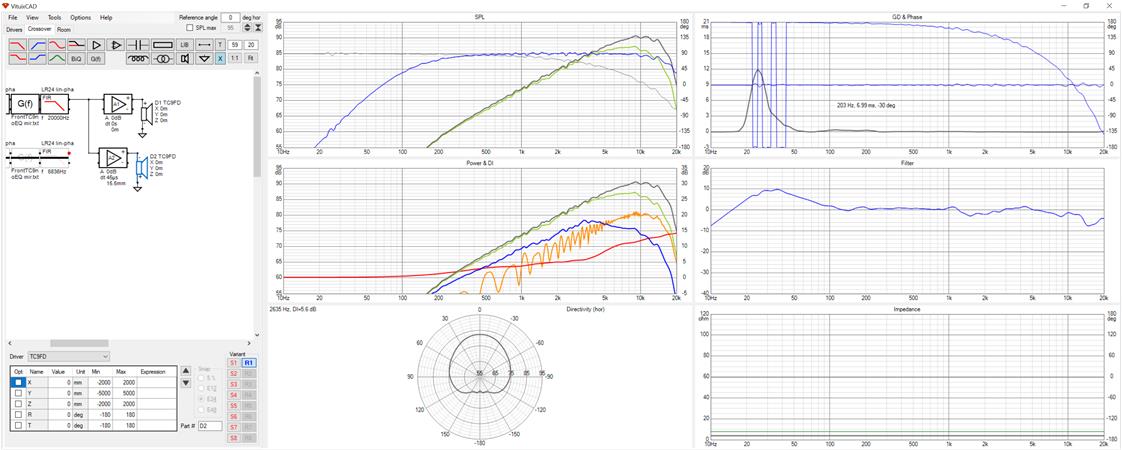
Is there something in Vituix that accounts for this or am I doing something wrong? I would love to be able to model dipole and active cardioid from single driver measurements or SPL trace + diffraction.
I tried to model dipole response with two drivers co-located and one driver fed an inverted signal delayed by the equivalent of 15mm thick baffle. The results are not what I expected.
I do see dipole rolloff and in directivity I see some suppression of radiation to sides and back but not the expected figure 8 response. I wonder if I'm doing something wrong. Its curious that the shape of the polar chart doesn't change when I mute/unmute the delayed driver. The same is true when I invert/un-invert that driver. Frequency response changes but not directivity shape (just magnitude)
Is there something in Vituix that accounts for this or am I doing something wrong? I would love to be able to model dipole and active cardioid from single driver measurements or SPL trace + diffraction.
Attachments
^If you are using simulated omni-directional response data or off-axis measurements (0-180 deg) of boxed driver:
- Add two drivers. Both have the same signal.
- Delay rear driver with Z mm parameter by sound travel distance difference between front and rear driver (towards listening spot). Typically baffle width / 2 + baffle thickness.
- Rotate rear driver 180 deg to aim it back.
- Invert rear driver.
- Add two drivers. Both have the same signal.
- Delay rear driver with Z mm parameter by sound travel distance difference between front and rear driver (towards listening spot). Typically baffle width / 2 + baffle thickness.
- Rotate rear driver 180 deg to aim it back.
- Invert rear driver.
Attachments
ease speakerlab naming convention i.e.; H010V035 ( 10 degrees horizontal, 35degrees.vertical).
This is done to rev 2.0.52.0. I tried to make parsing according EASE's documentation found in www: V[mmm]H[ppp] where V[mmm]=meridians and H[ppp]=parallels.
My interpretation is that V[mmm] is orbit (phi in CLIO) and H[ppp] is off-axis (theta in CLIO). Few examples:
- V000H060 => Hor 60 in VCAD
- V000H300 or V180H060 => Hor -60 in VCAD
- V090H060 => Ver 60 in VCAD
- V270H060 or V090H300 => Ver -60 in VCAD
I'm not entirely sure that it's correct. Could you verify is this okay?
^If you are using simulated omni-directional response data or off-axis measurements (0-180 deg) of boxed driver:
- Add two drivers. Both have the same signal.
- Delay rear driver with Z mm parameter by sound travel distance difference between front and rear driver (towards listening spot). Typically baffle width / 2 + baffle thickness.
- Rotate rear driver 180 deg to aim it back.
- Invert rear driver.
That was very helpful. I built up a dipole array model and it had less trouble with wall reflections than a monopole.
How would you model a cardiod? I tried adding a monopole behind the dipole but didn't get much directionality. I may be on the right track but its far from dialed in.
I figured I would ask a quick question here, as I'm using this great software.
I'm in the process of designing a set of 3-way speakers that I'm most likely going to use passive filters between TW - MR, and DSP between those and a W (4-channel amp).
What's most practical in your experience, just simulate and adjust the passive filter (TW/MR), or possibly simulate it as a passive 3-way..?
The drivers is simulated on the baffle, but I'm sort of unsure if I'm compensating something in the passive-filter that might be redundant or otherwise unpractical once I start to match the two responses (TW/MR<->W) in the DSP.
I hope I made some sense, and just a quick pointer is appreciated greatly.
How would you model a cardiod?
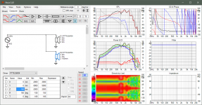
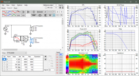
There are several ways to create simulated cardioid with actual or simulated measurement data. This one has two boxed drivers; one in front and another in back wall. Box depth 200 mm is entered to Z mm of rear driver and signal is inverted. Delay and required LP for rear driver (to prevent dipole pattern at HF) is done with single LR12 low-pass. Distance difference to virtual mic is compensated by dropping rear level a bit.
Attachments
Oh, on that notion it would be nice to have an active only version, where you could replace the impedance diagram with a copy of the directivity diagram. Than you can setup one for horizontal and one for vertical angles and keep an eye on both while equalizing without switching between them!Is it possible to add hidden option in "user.config" file for hiding active components from Crossover window? For people who will never use active components
An externally hosted image should be here but it was not working when we last tested it.
Does anyone know why this is giving strange errors? Incompatible Qts and alpha not less than <=0 ?
Also is there a way we can contribute to the online database?
kimmosto: Can you host the database on Github so it's easy for us to add drivers?
- Home
- Design & Build
- Software Tools
- VituixCAD