I have been experimenting with LT tonearms over the past 6-8 months, and have built 2 different LTA's with 4 different carriages. During this process I have learnt that a short stiff carriage/armwand is what is needed.
LTA 1 - Built as a proof of concept. This was about as good as my reference arm a Technics EPA100. Bass response was better and noise floor slightly lower. It struggled with stock bearings to track the Stanton 881s so I increased the diameter of the wheels which made a huge difference. Changed to my Technics EPC205mk2 with a Jico SAS.
LTA 2 - This is a total rip off of the Clear Audio TT1 and Niffy's carriage (the FROG). What this does amazingly is lower LP surface noise to levels I have never experienced, detail and dynamics are fabulous. Its issue is tracking off centre pressings where the voice has a lot of energy, I can hear distortion in each channel as the carriage moves back and forth. I built another carriage this time 20g lighter. This new carriage still has distortion on very heavily modulated tracks on the test LP, but I haven't heard it on music yet. It sounds great, but does have higher surface noise.
The reason I started this thread is I am considering building a motor driven LTA and I'm looking for others thoughts and ideas.
Goal is to duplicate LTA 2's FROG performance without the distortion tracking off centre pressings. Is this even possible
First decision is either mechanical servo like the Rabco or use an Adrino robotic controller?
Arm will be split effective mass like the Dynavector DV505. Main arm to be large and rigid with horizontal bearing and secondary arm on the end with vertical pivot.
Technics SL1200 bearings can be used for both pivots.
Carriage will run on 2x 8m linear rails in brass/bronze bushes.
Drive will be toothed belt driven by O rings
Drive motor 12V geared run at lower voltage to keep noise low
Attachments
Since you will be using a motorized system, will you be forcing the carriage / stylus into an off center lp movement and unable to "back off" from the rebound of the off center lp movement ? Perhaps some sort of clutch mechanism to disengage the motor drive when sensing excessive carriage movement is possible. Best of luck, I will be watching. I think Ralf ( Straight Tracker ) has the best overall tonearm concept that I know of.
Joe
Joe
No clutch needed as the main arm has a horizontal pivot. The simple idea is to copy the Rabco but move the vertical pivot to the end of the main arm. The motor will drive continuously and vary speed as the main arm pivots off tangent.
I think Ralph's Rabco uses a unipivot
I think Ralph's Rabco uses a unipivot
Technics SL1200 bearings can be used for both pivots.
Hello warrjon,
What are Technics SL1200 bearings?
Carriage will run on 2x 8m linear rails in brass/bronze bushes.
There may be too much friction involved without wheels of some kind.
Drive will be toothed belt driven by O rings.
As you know, toothed belts are used for timing or driving loads. If you use a wheeled carriage, an O-ring drive may be enough.
Drive motor 12V geared run at lower voltage to keep noise low
In the 1980s, I designed and built my first tangentially tracking tone arm.
Just prior to that, I had the chance to take a close look at a Goldmund tone arm, noticing that it used a Portescap gear motor to drive its carriage. In order for these small motors to produce a usable torque, they run at high speed and then are geared down to get the low RPM required to drive a tone arm's carriage. Well I didn't like that, so I designed a carriage driven by a 24 degree stepping motor from Airpax. I used a stepping motor driver from Sprague electric which is now Allegro Micro Systems. The motor drove the carriage via a silicon O-ring and that worked extremely well. The diameter of the O-ring was large enough to absorb the steps so that the carriage moved nice and smooth. I also borrowed from cutting lathe technology by using what is called "base pitch" which assumes that there always is a groove on the LP, spaced at the minimum pitch of .002".
To sense the tangency of the tone arm, I used a Hewlett_Packard HEDS-1000 optical sensor. However, these days I would use an analogue Hall Effect sensor from Allegro Micro Systems A1308 which can be actuated by a Neodimium magnet of diameter 2mmx2mm length. The Hall Effect sensor can be had for US$ 2-3. (cut tape) Of course you don't have to do it the way I did, but this will give you enough information to think about.
Sincerely,
Ralf
Hi Ralph,
Glad you chimed in I have read your thread on the servo pivoting arm. Before I commence buying bits and building I want to make sure I have a good chance of success.
Major decision is mechanical (Rabco style) or CPU controlled. I have emailed a local Robotics supplier to see how this could work. It's a LONG time since I did programming.
Technics SL1200 I meant tonearm bearings. These are very low starting torque but I am not sure if they will hold the heavy main arm. Maybe angular contact bearings???
I was looking at the Derenville LTA and it is driven with lead screw on linear rails although I can not see what the bearings are. I did consider linear bearings, but my current LTA bridge moves back on 12mm linear bearings (high quality industrial).
I was thinking today that if 2 hall sensors were used and the magnet between the sensors the CPU would know if the carriage was lagging/leading the arm.
Base pitch info is useful thanks, this will help set the base speed for the carriage.
Ralf,
I can’t speak for the Goldmund as I haven’t seen one to play with. The carriage drive motor on a Rabco SL8E is also a Portescap, 26mm. When running full speed with a 1.5 V battery the chain drive sprocket turns at 0.5455 RPM and, with a 1:560 gear ratio, the motor is turning 305 RPM which is indeed audible. At full speed, the carriage moves at around 1.3 inches/minute, which is way too fast so it starts/stops its way across the record with the characteristic crabbing motion that everyone complains about. I designed a photoelectric servo control modification for it
Rabco SL8E Photoelectric Servo Control Retrofit
that runs the motor continuously in a variable speed mode that just keeps up with the groove pitch. On a 20 minute record side the carriage drive motor spins around 40 RPM, at which speed it is quiet enough that you have to put your ear on the motor to hear that it is running at all. The motor has no trouble developing the needed torque to drive the carriage. The key thing I’ve learned is to run the carriage drive motor continuously ‘on’ to follow the average groove pitch instead of on/off start/stop. This way the motor runs smoothly and quietly. I adjust the tangency control so that it tracks at 90 deg for an average length LP, which I guess is somewhat akin to the “base pitch” concept you described for cutting lathes.
There are tradeoffs between going with a stepper motor or a DC gearmotor. The stepper route potholes include motor cogging, maybe the cost of micro-stepping controllers, and some type of digital control? It’s more complex but it’s a plus if you have microprocessor control because you can make the tonearm do almost anything, including scratch your nose for you while you inspect the stylus.
The dc gearmotor route potholes include high speed small motor noise (which can be ameliorated). On the plus side, this route can give you smooth, accurate, and jerk-free position control with a simple servo control circuit consisting of an opto-interrupter and a couple of transistors plus a few other parts. I have demonstrated the effectiveness of this approach with before-and-after YouTube videos in the link that I provided above.
Neither way is right or wrong but for me the simple control circuit is easier to diy and, except for cueing and other conveniences, will give audibly equivalent performance to a Dereneville LT on a blind test.
I looked up the HP HEDS-1000 and it looks like HP designed it for barcode scanner application and clean “on/off” signal generation. How did you interface that with the stepper motor? Did you use some form of soft start or ramp function control? I’d like to know more about how you did that one.
With my basic DC gearmotor servo-control drive I accomplished the continuous run characteristics by exploiting the orientation of the opto-interrupter aperture window with the arm flag motion to make it function as the analog gain element in the control loop.
Always interested in your thoughts.
Ray K
warrjon,
It looks like you are envisioning a linearized version of a Dynavector DV-505/7? If I were going through the trouble of starting from scratch (and I am working on something) I’d consider designing along the lines of a Revox Linatrack. I also advise seriously considering uni-directional servo control only and not invest heavily in the unnecessary complexity and headaches associated with making a bidirectional arm able to accurately follow record eccentricities both ways. Technology-wise it can be done, but there’s no payoff in doing it because the record is still off-center, which in itself causes tracking errors even if the arm is tracking a perfect 90deg. Let the arm wand pivot freely to handle the eccentricity like a regular pivoted arm.
Ray K
Since you will be using a motorized system, will you be forcing the carriage / stylus into an off center lp movement and unable to "back off" from the rebound of the off center lp movement ?
Joe
Joe,
The motorized servo system is not "forcing" the carriage/stylus to do anything worse in handling off center LP movement than the way a conventional pivoted arm does. If anything, carriage/stylus "forcing" on eccentricities is a problem with purely mechanical LT's, because the eccentricities deflecting a cantilever "winds up" the suspension spring and slingshots the carriage forward when the bearing stiction let's go, at which point it overshoots the suspension 'neutral' point. Freely pivoting servo controlled arms don't do that. Please go re-read my post #3683 in the other thread, and my other comments regarding servos.
Ray K
diyrayk,
Thanks for the clarification. It is amazing what you can do with some knowledge and modern electronics. Looking at and watching Ralf's arm negotiate record groves was a real eye opener !!! Not to mention his amazing craftsmanship !! Best of luck with your design.
Joe
Thanks for the clarification. It is amazing what you can do with some knowledge and modern electronics. Looking at and watching Ralf's arm negotiate record groves was a real eye opener !!! Not to mention his amazing craftsmanship !! Best of luck with your design.
Joe
I was hoping you and Ralph would add your experience with servo LTA's. I have the mechanical working exceptionally well on good pressings but on anything with a lot of modulation (female voice especially) and off centre I can hear distortion that is not there on my Technics arm so I know it's carriage inertia causing this.
My idea with the DV505 style is to split the vertical and horizontal effective mass. I hadn't considered the Revox style so I asked Dr Google and a mate who has a Revox B795. The Revox style arm maybe a better approach.
Revox B790 - YouTube
I did look at both uni and bipolar steppers run with an Arduino but I think I will use a geared DC motor and a similar setup to your Rabco to start with. My Ultrasonic record cleaner runs a 0.6rpm geared DC motor doing 0.09rpm at 2volts and the motor noise is so low you need to put ear very near the motor to hear it and still has enough torque to rotate 2x 12" LP's. So I thought if I drive a 12v motor at somewhere between 2 and 4 volts, this could work. This will be unidirectional I was not thinking of driving the carriage backwards, I this could be fraught with problems.
I like the very short arm wand of the Revox, the arm could be made from carbon fibre. just need to work out the best bearing arrangement, What are your thoughts on using a knife edge for the vertical.
cheers Warren
warrjon,
If I were going through the trouble of starting from scratch (and I am working on something) I’d consider designing along the lines of a Revox Linatrack.
Ray K
Hi Ray,
Been thinking about this, the only down side I can come up with at the moment is carriage damping. I was going to use a silicon oil bath to dampen arm resonance with the Rabco style. The Revox short arm would require this over the LP?
Any thoughts.
cheers Warren
I looked up the HP HEDS-1000 and it looks like HP designed it for barcode scanner application and clean “on/off” signal generation. How did you interface that with the stepper motor? Did you use some form of soft start or ramp function control? I’d like to know more about how you did that one.
Hello Ray,
A lot of thought went into that tone arm. Tomorrow I'll find the schematic and post it. I don't want to hijack this new thread and I wondered if anyone might be interested in a new thread describing my forty year old tangential tone arm?
Sincerely,
Ralf
Hi Ralf,
I started this thread so we can exchange ideas on servo driven arms, anything that helps me now and others in the future design a functional servo arm is what this is about so please feel free to post it here.
I started this thread so we can exchange ideas on servo driven arms, anything that helps me now and others in the future design a functional servo arm is what this is about so please feel free to post it here.
Hi Ray,
Been thinking about this, the only down side I can come up with at the moment is carriage damping. I was going to use a silicon oil bath to dampen arm resonance with the Rabco style. The Revox short arm would require this over the LP?
Any thoughts.
cheers Warren
Warren,
As a diy’er I am partial to unipivot bearings. They are easy to make. They have low friction. They are automatically preloaded to the correct amount just by sitting there. It is very easy to incorporate viscous damping as an integral part of the unipivot design. If you put a unipivot arm on a servo driven carriage and get rid of the offset angle, all stylus drag forces and vertical warp induced forces are in the same plane as the unipivot bearing, so there is no residual torque causing azimuth shift.
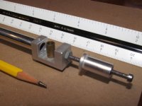
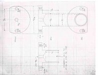
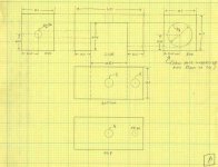
These are the sketches from my arm. It uses an inverted brass cup bearing (part B) that sits atop a high speed steel rod with a ground point. The cup bearing is press-fit into an aluminum yoke (part A) to which the arm tube and counterweight support are attached. The steel rod is press-fit into a brass cup/base (part C) with the point upward and the brass cup/base is half filled with silicone damping fluid. Sorry, I never got a picture of the finished rod assembled into the cup/base. Unlike outrigger oil trough dampers that are applied to conventional arms as an afterthought, the silicone fluid used here is thick and will not spill or run, even if you turn the whole assembly upside down for several minutes. I would have no qualms with something like this hovering over the LP.
https://www.diyaudio.com/forums/attachment.php?attachmentid=862061&stc=1&d=1595214211
All parts
https://www.diyaudio.com/forums/attachment.php?attachmentid=862062&stc=1&d=1595214211
Part 'A'
https://www.diyaudio.com/forums/attachment.php?attachmentid=862063&stc=1&d=1595214211
Part 'B'
https://www.diyaudio.com/forums/attachment.php?attachmentid=862064&stc=1&d=1595214211
Part 'C'
https://www.diyaudio.com/forums/attachment.php?attachmentid=862065&stc=1&d=1595214211
Parts 'A' and 'B' assembled
Ray K
Attachments
Thanks Ray,
This could be a good start, although I have never used a unipivot before, I have just about everything in the scrap bin to make this.
Can I ask how long the pin is compared to the depth of the trough and what CST silicon oil you used.
This could be a good start, although I have never used a unipivot before, I have just about everything in the scrap bin to make this.
Can I ask how long the pin is compared to the depth of the trough and what CST silicon oil you used.
Hello Warren and Ray,
It took several days to find those 35 year old files. Tomorrow I'll post them along with a picture of the printed circuit board.
Sincerely,
Ralf
It took several days to find those 35 year old files. Tomorrow I'll post them along with a picture of the printed circuit board.
Sincerely,
Ralf
I have ordered all the bits to motorise the carriage using an Arduino and a geared motor. Time to learn to program.
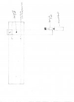
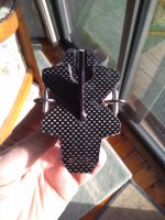
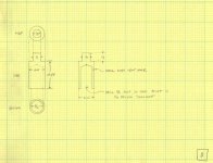
Did a quick sketch of a unipivot to run on the rail. Dual carbon fibre tubes to increase rigidity and the arm wand will be removable, clamped by the 2 vertical bolts in the top.
Plan is to use 2x MGN9 rails under the carriage, this will leave the arm with nothing over the top so as to make setting up and changes easy
Does anyone have opinions on carriage drive my thoughts are lead screw with nylon nut or toothed belt.
Attachments
Hello Warren and Ray,
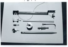
I finally got my files together. I think I'll post the pictures first and type a description after that.
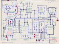
I controlled the tangency of my first tone arm with an HP HEDS-1000 optical sensor. the target was a membrane of chrome mylar with half of it painted flat black. The analog output of the HEDS-1000 was applied to a voltage controlled oscillator. The VCO was supposed to be able to output frequencies as low as .1Hz. However, I could never obtain that low a frequency from that IC. So I used two "divide by ten" ICs and then applied that signal to a Sprague Electric UCN 4202A stepper motor driver to drive the carriage motor.
Not having any test equipment, I provided a digital display on the front of the control housing to alternately show a one and a zero every time the motor took a step. Then I played steady state tones from a CBS test record and listened to variations in pitch every time the carriage motor took a step. That was an excellent test, because I have always been sensitive to variations in pitch. (it drives me nuts if I can't tune my guitar just right) The Sprague Electric IC UDN 5707A is the driver for the seven segment display on the front of my control housing. The carriage was moved by two silicon o-rings and they effectively absorbed the shocks from the stepping motor.
Other circuits included on the circuit board, are TTL logic ICs to control the tone arm lift motor. They made sure that, the carriage motor would not run when the tone arm was being lifted and vice versa.
I did not design the circuit myself. I had major help from Richard H., an engineer at Scully Recording Instruments in Connecticut where I worked at the time.
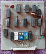
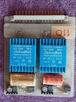
And I almost forgot: the PCB on the right is the 5 and 12v power supply, 5v for the TTL logic ICs and 12v for the Airpax stepping motor.
Sincerely,
Ralf
I finally got my files together. I think I'll post the pictures first and type a description after that.
I controlled the tangency of my first tone arm with an HP HEDS-1000 optical sensor. the target was a membrane of chrome mylar with half of it painted flat black. The analog output of the HEDS-1000 was applied to a voltage controlled oscillator. The VCO was supposed to be able to output frequencies as low as .1Hz. However, I could never obtain that low a frequency from that IC. So I used two "divide by ten" ICs and then applied that signal to a Sprague Electric UCN 4202A stepper motor driver to drive the carriage motor.
Not having any test equipment, I provided a digital display on the front of the control housing to alternately show a one and a zero every time the motor took a step. Then I played steady state tones from a CBS test record and listened to variations in pitch every time the carriage motor took a step. That was an excellent test, because I have always been sensitive to variations in pitch. (it drives me nuts if I can't tune my guitar just right) The Sprague Electric IC UDN 5707A is the driver for the seven segment display on the front of my control housing. The carriage was moved by two silicon o-rings and they effectively absorbed the shocks from the stepping motor.
Other circuits included on the circuit board, are TTL logic ICs to control the tone arm lift motor. They made sure that, the carriage motor would not run when the tone arm was being lifted and vice versa.
I did not design the circuit myself. I had major help from Richard H., an engineer at Scully Recording Instruments in Connecticut where I worked at the time.
And I almost forgot: the PCB on the right is the 5 and 12v power supply, 5v for the TTL logic ICs and 12v for the Airpax stepping motor.
Sincerely,
Ralf
Attachments
Last edited:
- Home
- Source & Line
- Analogue Source
- DIY Servo driven Linear tonearm