Ralf,
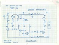
Thanks for sharing your control schematic. As I see it, the drive can be done digital with with a stepper motor or analog with a DC motor. Small stepper motors are readily available at low cost, but the drive circuit is more complex. A DC motor drive is simpler, but quality [quiet] gearmotors like Maxon or Portescap in high reduction ratios are not so easy to find at diy affordable prices. When I designed a retrofit photoelectric control circuit for a Rabco SL8E, which came with Portescap motors, I naturally went with an analog circuit. My first was for a radical mechanical/electrical modification and my second was for a more restrained 'aftermarket' approach.
The first one:
https://www.diyaudio.com/forums/attachment.php?attachmentid=865342&stc=1&d=1596403531
The second one:
https://www.diyaudio.com/forums/attachment.php?attachmentid=865343&stc=1&d=1596403623
The difference in the two schematics is the first one is actuated by ‘allowing’ the beam and the second one is actuated by ‘interrupting’ the beam. I posted construction details of my second circuit here:
Rabco SL8E Photoelectric Servo Control Retrofit
but that thread has so far not generated much interest.
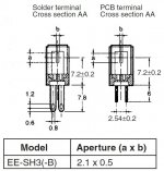
In order to achieve ‘soft’ control and get away from on/off jackrabbit operation I oriented the opto-sensor aperture 90 degrees so the interrupting flag sweeps across the aperture like a solar eclipse, vertically along the ‘a’ dimension here:
https://www.diyaudio.com/forums/attachment.php?attachmentid=865344&stc=1&d=1596403698
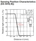
The circuit components were selected to put the operating point at the middle of the sensitivity curve for an average groove pitch:
https://www.diyaudio.com/forums/attachment.php?attachmentid=865345&stc=1&d=1596403737
The net effect of rotating the aperture is to widen the slope of the line. I selected fixed value resistors instead of adjustable trimpots because of space limitations, the tradeoff being not able to easily adjust/tweak the circuit. In comparing with your circuit, it looks to me like your ‘base pitch’ trimpot function effect is similar to me tweaking my circuit values to operate near the center of the slope, and I’m guessing that your ‘expansion’ trimpot has the effect of adjusting the slope of the line. I like the concept of doing it this way because the deviation of the error correction circuit is referenced to an average groove pitch (i.e., the carriage motor runs continuously), which is easier to control and pretty much eliminates stiction issues in the mechanical drive. I hope I’m understanding the operation of your circuit correctly.
Ray K
Thanks for sharing your control schematic. As I see it, the drive can be done digital with with a stepper motor or analog with a DC motor. Small stepper motors are readily available at low cost, but the drive circuit is more complex. A DC motor drive is simpler, but quality [quiet] gearmotors like Maxon or Portescap in high reduction ratios are not so easy to find at diy affordable prices. When I designed a retrofit photoelectric control circuit for a Rabco SL8E, which came with Portescap motors, I naturally went with an analog circuit. My first was for a radical mechanical/electrical modification and my second was for a more restrained 'aftermarket' approach.
The first one:
https://www.diyaudio.com/forums/attachment.php?attachmentid=865342&stc=1&d=1596403531
The second one:
https://www.diyaudio.com/forums/attachment.php?attachmentid=865343&stc=1&d=1596403623
The difference in the two schematics is the first one is actuated by ‘allowing’ the beam and the second one is actuated by ‘interrupting’ the beam. I posted construction details of my second circuit here:
Rabco SL8E Photoelectric Servo Control Retrofit
but that thread has so far not generated much interest.
In order to achieve ‘soft’ control and get away from on/off jackrabbit operation I oriented the opto-sensor aperture 90 degrees so the interrupting flag sweeps across the aperture like a solar eclipse, vertically along the ‘a’ dimension here:
https://www.diyaudio.com/forums/attachment.php?attachmentid=865344&stc=1&d=1596403698
The circuit components were selected to put the operating point at the middle of the sensitivity curve for an average groove pitch:
https://www.diyaudio.com/forums/attachment.php?attachmentid=865345&stc=1&d=1596403737
The net effect of rotating the aperture is to widen the slope of the line. I selected fixed value resistors instead of adjustable trimpots because of space limitations, the tradeoff being not able to easily adjust/tweak the circuit. In comparing with your circuit, it looks to me like your ‘base pitch’ trimpot function effect is similar to me tweaking my circuit values to operate near the center of the slope, and I’m guessing that your ‘expansion’ trimpot has the effect of adjusting the slope of the line. I like the concept of doing it this way because the deviation of the error correction circuit is referenced to an average groove pitch (i.e., the carriage motor runs continuously), which is easier to control and pretty much eliminates stiction issues in the mechanical drive. I hope I’m understanding the operation of your circuit correctly.
Ray K
Attachments
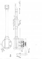
![Schematic [org].jpg](/community/data/attachments/786/786877-4687705ab465633a20f80c7d9e9da436.jpg?hash=RodwWrRlYz)
Warren,
Don't interpret my lack of posting for a while as losing interest. I have been thinking about the design ideas bantered about so far. I've re-read posts in the other threads about the merits of short arms. Let's accept for the moment the likelihood that shorter arms contribute to better resonance integrity vis-a-vis bending modes. The bane of PLT's is that every PLT design studied so far introduces some skating force, and all the side force issues that come with that. The bane of mechanical linear trackers is lateral friction and stiction, and often vague vertical pivot definition. Careful analysis of YouTube videos of MLT's in action invariably show severe to barely perceptible cantilever deflection on record eccentricities. IMO "barely perceptible" in the micron world of the stylus always puts it in the "severe" category. Air bearing LT's score well in the friction/stiction department, but they have other difficulties to deal with, and are really difficult to diy.
I think Ralf with his servo designs and, at the risk of sounding immodest, I and my own servo control circuits that I have built and posted have demonstrated that active servo controls can operate imperceptively if designed and built right, and that popular anti-servo arguments are bunk. I'm confident it can be made to work quite well with either approach.
Having said that, and staring at a blank sheet of paper, I see two prime diy concepts. One is essentially a Dynavector DV-505/507 converted to a straight DJ arm by eliminating the offset angle with tracking error correction achieved by moving the arm pivot on a servo controlled slide, along the lines of your original sketch.
The second is essentially ripping off the ReVox Linatrack design. On closer inspection I think the magnet/unipivot suspension design is more difficult to pull off than I first realized. My concern with that short of an arm is that it 'amplifies' the need for really smooth and precise servo control, which pushes it towards the 'hard to diy' end of the spectrum. I was rather surprised by the extent of the cantilever deflection that can be seen in the video you found, especially easy to see at the beginning. Maybe it needs service:
Revox B790 - YouTube
So, the most viable candidate might be some variant of the Dynavector split-pivot design like you sketched in your OP. Putting the horizontal pivot way back on the servo carriage provides the leverage for the stylus to move the arm laterally without cantilever deflection, thus knocking out the sideways friction/stiction issue of the mechanical LT's. Not sure about the effects of the vertical cwt adding to the horizontal mass. The vertical articulation can be achieved a number of ways depending on design preference and parts on hand. The only catch is how to apply a modest amount of damping on the bearings.
Thinking, thinking, thinking...
Ray K
Hi Ray,
Thanks for the thoughts, keep them coming. Before I commence machining of the arm I want to ensure I have the best possible solution. I have designed the rail bridge to enable arms to be swapped so changing from a unipivot to DV505 style will be possible.
I am currently working on the drive circuitry using an Arduino to control a DC geared motor with a photo interupter as the position sensor. This is working well except for the low speed motor noise/vibration as it's a cheap eBay dc motor. I have it working with sensor speed control for LP playback and a carriage limit switch that send the carriage back home programmable up to full speed.
I have been unable to source a quality geared DC motor here in Aus so I purchased a NEMA11 1.8deg stepper motor and micro step controller driven by the Arduino to try out. Boy these are cheap now total outlay for motor, step controller and Arduino under $100AUD.
After your last post about the unipivot I sketched up a Graham style unipivot with damping. This still has the arm wand at around 170mm.
I have never heard the Dynavector, but it's interesting Dereneville had one installed along with their linear on the test bed TT.
I have also given a lot of thought to damping the DV style. Which ever way I go I am planning on having the senor at the end of a fixed wand like the Goldmund, this will provide a mounting place for a damping bucket and damping can be applied at the headshell.
Still have not decided on the rail yet. I found this at RS Components. I am leaning towards this rail as it has no ball bearings. It uses composite slides in the carriage. Your thoughts???
TW-04-09 | Igus Linear Guide Carriage TW-04-09, T | RS Components
Attachments
Warren,
FWIW I bought one of these linear lead-screw modules from Amazon to play with:
Q-module 195 mm Integrated Linear Lead-screw system - 1 set: Amazon.com
Current price is $50. I paid $5 shipping. It took about 6 weeks delivery and I think they come from China. The build quality is actually quite nice, smooth operation, adjustable backlash on the leadscrew end bearings (ball). The leadscrew "nut" is an integral part of the plastic slide and the pre-load on that is adjustable, too.
Ray K
I just bought one of those rails off eBay, about the same price it's coming from Cyprus. Hopefully it'll get here.
I also bought a few NOS HDD bearing cartridges to try for the vertical pivot. These are ultra high precision bearings.
I also bought a few NOS HDD bearing cartridges to try for the vertical pivot. These are ultra high precision bearings.
Quick update....
I have most of the Arduino code for DC motor and switch control written and working. Semi automatic so push a button to move arm to LP start and then hit Cue button, end of LP raises the arm and returns the arm to home.
The NEMA 11 stepper motor arrived today so next is to integrate in place of the DC motor.
Once I get this operational I will make the code available to the DIY community.
Code is now completely automated and running the stepper motor on the bench.
Start button sends arm to LP start then pulses the cue motor, This is for 12" only, but can be changed by adding additional interlock switches and selector switch for 10" and 7".
Arm lift will be similar to the Rabco using a reed switch, with arm lift at LP end outside of Arduino control, this is a fail safe in case anything fails the arm will lift as long as the cue motor has power.
Arm will lift at LP end and return to the home position automatically. There are also manual forward, reverse and cue functions.
Next is to build a protoytpe once the linear module arrives.
Need some input guys.
I am heavily leaning towards a Dynavector split effective mass arm. What I am struggling with is how to implement a cue mechanism.
The cue needs to centre the main arm before lifting the stub arm. It needs to use a motor (like the Rabco) as this is easy to implement in the code as a single pulse will cue up and down, whereas a solenoid needs pick and hold.
BTW the rail only arrive a week ago.
questions ?
"I am heavily leaning towards a Dynavector split effective mass arm"
Which one ?
And why?
dennis h
"I am heavily leaning towards a Dynavector split effective mass arm"
Which one ?
And why?
dennis h
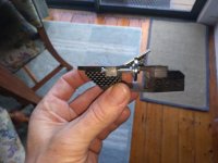
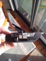
I was planning on building my own DV505 style arm. The difference is I was not going to use a bearing for the vertical pivot. I was planning on using a Transfi Terminator style pin pivot. Bearings chatter however small will colour the sound and removing as many sources of resonance as possible does improve the ability of the system to retrieve detail. My current LTA I have used both bearings and pin pivots, the pin pivots are measurably better (less resonance).
The advantage is a very short stiff arm wand, which reduces ringing and resonance. My current MLT uses a 99mm carriage which is extremely stiff. The bass response and detail this retrieves is the best I have heard in a TT system. I was trying to integrate a smaller version of this carriage into a DV style main arm, unsuccessfully at this stage only due to cueing.
My question was to address an issue with running a cueing mechanism down the main arm wand. I see this mechanism as a source of resonance. My other issue was that the main arm needs to be centred after the secondary arm is lifted, I wrote before in my last post but this is incorrect. Not centering the main arm will cause issues when the arm is cued down, it's possible for the arm to way off centre this could cause skipping at best or stylus damage worst case.
The first pic the carriage has bearings and 2nd pic pin pivots.
.
Attachments
Last edited:
I vote for the pin pivots. Think of it as two unipivots in tandem - inherently correct preload and no loose parts to vibrate as in a ball bearing.
Ray K
Ray K
Hi Ray,
Yes I am pro pin pivots, I just can't work out an acceptable method to cue the secondary arm. The cueing mechanism becomes overly complex.
I have given this a great deal of thought and a unipivot will be easier to implement.
On a different note, I have found the stepper driver that Dereneville use in their LTA, it's a TMC2100 which almost silences the stepper motor.
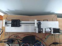
Video of the carriage with 2 different stepper drivers. The 1st minute is a standard driver, 2nd minute is with a TMC2100 which is the same driver used in the Dereneville. It is almost totally silent when the carriage is moving at LP play speed, I can just hear some motor noise with a stethoscope on the carriage block. Next is to isolate the motor from the frame with rubber mounts.
The large aluminium coupling off the motor is a magnetic clutch, uses 5 neodymium magnets and is strong. To mount the motor with rubber grommets I need to move the motor and drive the clutch with a belt as the magnetic clutch is so strong it pulls the couplings together. The clutch works as it slips when the carriage hits the end.
DIY stepper driven linear tonearm - YouTube
Hi Warren,
I like where this is going. A couple of comments/questions , if I may.
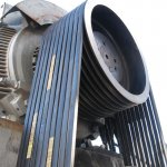
The weight on the slide looks like a hunk of steel that must be as heavy as a bowling ball. That, the three belts, and rather large size of stepper motor reminded me of a high horsepower multiple v-belt industrial drive:

Admirable capability, but maybe a little overkill? The heavy mass might be smoothing out mechanical pulsing from the stepper motor and so, counterintuitively, it might be a greater challenge to make the stepper drive pulse-free with a more realistic lighter weight of a tonearm on the slide. I haven't experimented with stepper motors yet. I'm very interested in the reduction of noise/pulsing you obtained with the TMC2100 driver. Is that a so-called "microstepper"? My understanding is that microsteppers adjust the relative current between the two phases so that the rotor can be held at intermediate positions/steps between poles. Is this a built-in function of the driver, or does the arduino handle that?
Ray K
I like where this is going. A couple of comments/questions , if I may.
The weight on the slide looks like a hunk of steel that must be as heavy as a bowling ball. That, the three belts, and rather large size of stepper motor reminded me of a high horsepower multiple v-belt industrial drive:
Admirable capability, but maybe a little overkill? The heavy mass might be smoothing out mechanical pulsing from the stepper motor and so, counterintuitively, it might be a greater challenge to make the stepper drive pulse-free with a more realistic lighter weight of a tonearm on the slide. I haven't experimented with stepper motors yet. I'm very interested in the reduction of noise/pulsing you obtained with the TMC2100 driver. Is that a so-called "microstepper"? My understanding is that microsteppers adjust the relative current between the two phases so that the rotor can be held at intermediate positions/steps between poles. Is this a built-in function of the driver, or does the arduino handle that?
Ray K
Attachments
Hi Ray,
The weight on the carriage is about 5kg, and I used it only to test that the carriage did not stall with load. The stepper motor is a NEMA 11 which is about the smallest stepper available. I had to gear the motor up so motor RPM dropped for the same carriage travel as the motor was stalling mostly at high speed return.
The belt drive is designed as a 1:2 gear step up and to reduce vibrations from getting to the carriage. I stole this idea and the magnetic clutch from Dereneville.
The TMC2100 is a standalone driver and only needs direction and pulse (step) from the Arduino. It's configurable for 2 modes spreadCycle and stealthChop and up to 1/16 micro stepping. I am running stealthChop with 1/16 micro stepping. Basically you can feed a squarewave into the TMC2100 ground the DIR pin and the motor will move. stealthChop according to the datasheet uses hysteresis in the PWM to stop the motor from oscillating which causes the noise.
The Arduino's main job is to control stepping of the motor with the input of the photo sensor and drive the carriage back and forth with switches. The way I have programmed the Arduino is to step the carriage X steps when the photo sensor voltage is >= X volts. X will be tuned once I have the whole arm mounted and operational.
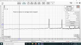
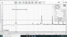
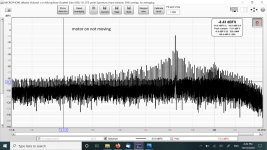
I did some testing looking at the spectrum analysis with no load on the carriage, ie the weight removed. The screen shots show the motor running at play speed with no load on the carriage. I am happy these artifacts will be below the noise floor once the arm is playing an un-modulated groove, but I will re-test when finished.
These measurements were taken on the carriage using an MM cartridge fed directly into a Focusrite Solo. I did these to decide if I needed to mount the motor on rubber isolation, but I think will go with what I have for the moment and re-measure once the arm is complete.
The weight on the carriage is about 5kg, and I used it only to test that the carriage did not stall with load. The stepper motor is a NEMA 11 which is about the smallest stepper available. I had to gear the motor up so motor RPM dropped for the same carriage travel as the motor was stalling mostly at high speed return.
The belt drive is designed as a 1:2 gear step up and to reduce vibrations from getting to the carriage. I stole this idea and the magnetic clutch from Dereneville.
The TMC2100 is a standalone driver and only needs direction and pulse (step) from the Arduino. It's configurable for 2 modes spreadCycle and stealthChop and up to 1/16 micro stepping. I am running stealthChop with 1/16 micro stepping. Basically you can feed a squarewave into the TMC2100 ground the DIR pin and the motor will move. stealthChop according to the datasheet uses hysteresis in the PWM to stop the motor from oscillating which causes the noise.
The Arduino's main job is to control stepping of the motor with the input of the photo sensor and drive the carriage back and forth with switches. The way I have programmed the Arduino is to step the carriage X steps when the photo sensor voltage is >= X volts. X will be tuned once I have the whole arm mounted and operational.
I did some testing looking at the spectrum analysis with no load on the carriage, ie the weight removed. The screen shots show the motor running at play speed with no load on the carriage. I am happy these artifacts will be below the noise floor once the arm is playing an un-modulated groove, but I will re-test when finished.
These measurements were taken on the carriage using an MM cartridge fed directly into a Focusrite Solo. I did these to decide if I needed to mount the motor on rubber isolation, but I think will go with what I have for the moment and re-measure once the arm is complete.
Attachments

As part of my long term, and ongoing search for the perfect motor drive system, I was wondering if the TMC driver chip might be used with its full 256 microstepping capability to drive a stepper motor smoothly enough to use as belt drive motor.
From what I've seen, one of the the results of the microstepping is a very good simulation of a sine wave drive.
Any thoughts?
From what I've seen, one of the the results of the microstepping is a very good simulation of a sine wave drive.
Any thoughts?
Hi Ralph,
I am using 1/16 ustepping with 256 interpolation this is the default configuration for most TMC PCB's except the one I bought, I had to cut a trace on the PCB. These things are so small it was like micro surgery. What the TMC adds is hysteresis in the PWM signal which further smooths the drive signal. At play speed the motor is almost totally silent I needed to put my ear very nearly on the motor to hear it. Fast forward/reverse the noise is dominated by mechanical noise of the rail and drive system.
Without the TMC2100 driver a stepper driven tonearm would be a nogo. The stepper motor even with 6400 ustepping is just too noisy. These days a BLDC motor maybe a better choice. I chose the stepper motor to drive the carriage very slowly at play speed and return the carriage home in about 15 seconds this requires a speed variation between 5 to 450 rpm not possible with a brushed DC motor as it did not have enough torque to drive the carriage at 5rpm, a BLDC motor geared correctly would most likely do this.
Thanks for the info, I've ordered a few pieces to experiment with. I suspect you're right wrt BLDC motors, but I do like to investigate 'the path less travelled'.
- Home
- Source & Line
- Analogue Source
- DIY Servo driven Linear tonearm