Hi.
I just have finished my build and run in to troubles while setting bias.
The highest value of bias that I can set is around 120mv (after an hour of warming the thing up).
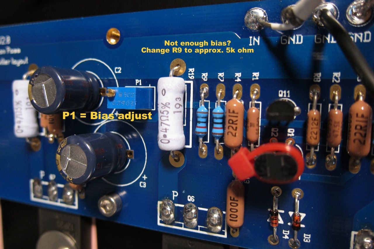
I used the resistor values as in the first page in this thread: R8=22.1K, R9=10k and P1=5k. I believe that R8 or R9 should be changed. am I right? what values should I use?
And the other problem is that one of the voltages across the 0.47ohm resistors is way off.
In first channel the voltages on resistors connected to P transistors are: 127mV, 116mV and 135 mV and on N transistors 128mV, 128mV and 123mV,
On second channel the voltages on resistors connected to P transistors are : 142mV, 142mV and 76mV (!!) and on N transistors: 118mV, 121 mV, 120mV.
Are the differences in voltage values on first channel acceptable?
The second channel is obviously not ok. Is it caused by a badly matched transistor?
I have bought the transistor set here on diyaudio store.
I am asking for your help in solving this.
I just have finished my build and run in to troubles while setting bias.
The highest value of bias that I can set is around 120mv (after an hour of warming the thing up).
I used the resistor values as in the first page in this thread: R8=22.1K, R9=10k and P1=5k. I believe that R8 or R9 should be changed. am I right? what values should I use?
And the other problem is that one of the voltages across the 0.47ohm resistors is way off.
In first channel the voltages on resistors connected to P transistors are: 127mV, 116mV and 135 mV and on N transistors 128mV, 128mV and 123mV,
On second channel the voltages on resistors connected to P transistors are : 142mV, 142mV and 76mV (!!) and on N transistors: 118mV, 121 mV, 120mV.
Are the differences in voltage values on first channel acceptable?
The second channel is obviously not ok. Is it caused by a badly matched transistor?
I have bought the transistor set here on diyaudio store.
I am asking for your help in solving this.
Hi.
I just have finished my build and run in to troubles while setting bias.
The highest value of bias that I can set is around 120mv (after an hour of warming the thing up).
I used the resistor values as in the first page in this thread: R8=22.1K, R9=10k and P1=5k. I believe that R8 or R9 should be changed. am I right? what values should I use?
And the other problem is that one of the voltages across the 0.47ohm resistors is way off.
In first channel the voltages on resistors connected to P transistors are: 127mV, 116mV and 135 mV and on N transistors 128mV, 128mV and 123mV,
On second channel the voltages on resistors connected to P transistors are : 142mV, 142mV and 76mV (!!) and on N transistors: 118mV, 121 mV, 120mV.
Are the differences in voltage values on first channel acceptable?
The second channel is obviously not ok. Is it caused by a badly matched transistor?
I have bought the transistor set here on diyaudio store.
I am asking for your help in solving this.
first channel P mosfets are nicely matched
second channel P mosfets are badly matched, you need properly matched ones
Thank you!
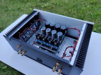
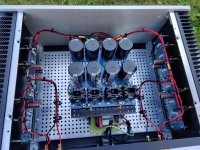
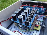
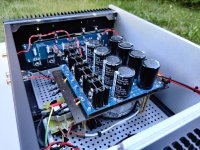
And here are some pictures...
And here are some pictures...
Attachments
-
 IMG_20200710_164406.jpg610.7 KB · Views: 297
 -
 IMG_20200710_164418.jpg569.1 KB · Views: 285
 -
 IMG_20200710_164434.jpg621.2 KB · Views: 277
 -
 IMG_20200710_164443.jpg661.8 KB · Views: 289
 -
 IMG_20200710_164458.jpg568.6 KB · Views: 178
 -
 IMG_20200710_164608.jpg409.8 KB · Views: 173
 -
 IMG_20200710_164651.jpg726.5 KB · Views: 175

I will....
But now I am fighting with transistors.
I have replaced a few of them Now when I mesure voltages on 0.47 0hm resistors connected to P transistors I get 183 mV, 207mV and 203mV.
Are those values acceptable?
But now I am fighting with transistors.
I have replaced a few of them Now when I mesure voltages on 0.47 0hm resistors connected to P transistors I get 183 mV, 207mV and 203mV.
Are those values acceptable?
I will....
But now I am fighting with transistors.
I have replaced a few of them Now when I mesure voltages on 0.47 0hm resistors connected to P transistors I get 183 mV, 207mV and 203mV.
Are those values acceptable?
Are those cold or warmed up numbers?
Hi all,
For those who bought the 4U chassis from DIY Audio store, can you please let me know how you mount the feet? I also bought the anti-vibration feet option for the chassis.
Here are some pics. I wonder if I am doing something wrong. Instructions included with the shipment is for a 5U chassis. Thanks!


For those who bought the 4U chassis from DIY Audio store, can you please let me know how you mount the feet? I also bought the anti-vibration feet option for the chassis.
Here are some pics. I wonder if I am doing something wrong. Instructions included with the shipment is for a 5U chassis. Thanks!
An externally hosted image should be here but it was not working when we last tested it.
An externally hosted image should be here but it was not working when we last tested it.
Last edited:
Hi! Yes, so it seems that the screws provided in the kit are too short. What about the anti-vibration feet. Does anyone ordered this option for the 4U and if so, can you please share how you installed it? Thank you!
Last edited:
I made extra holes in the black bottom cover.
Btw. The design is not well thought out. If you are using a montage plate, disassembly the side heat sinks, for example to replace elements, is a nightmare. you have to take everything down to zero....
Btw. The design is not well thought out. If you are using a montage plate, disassembly the side heat sinks, for example to replace elements, is a nightmare. you have to take everything down to zero....
I made extra holes in the black bottom cover.
Btw. The design is not well thought out. If you are using a montage plate, disassembly the side heat sinks, for example to replace elements, is a nightmare. you have to take everything down to zero....
I see. Thank you! Wonder why the anti-vibration feet is part of the option for the chassis kit but you need to drill holes to install them?
I think that you are right. Please see pics below.Maybe they can be installed differently. But I thought that it would be the best option.
Optional anti-vibration feet
An externally hosted image should be here but it was not working when we last tested it.
We know that the base plate is attached to the pillar with M3 screws. The anti-vibration feet option comes with I think M5 male bolt protruding about say 5mm. That alone shows mis-match.
An externally hosted image should be here but it was not working when we last tested it.
An externally hosted image should be here but it was not working when we last tested it.
An externally hosted image should be here but it was not working when we last tested it.
I believe that in order to install the feet without drilling a hole, the M5 bolt needs to be pulled out from the rubber feet center and replaced by a longer M3 bolt, secured to the rubber feet, that will pass through the isolator, cap, base plate, then screws in to the pillar. That's all I can think of.
- Home
- Amplifiers
- Pass Labs
- A guide to building the Pass F4 amplifier