Sorry, Kees, I don't buy it. This is even what Mr. Panzer recommends and also there's an example horn project utilizing this very method. And I really can't see how it could be wrong - technically. It's just a shape of the outer shell that is different.
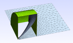
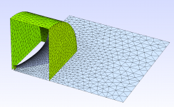
The outer cylinder extended 5 mm past the throat, so the whole interior is now enclosed in the outer shell (however irrelevant that is) -
Attachments

Last edited:
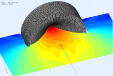
My attempt to explain the worse behaviour for the longer tube is that due to the presence of the tube the SPL falls slower to the sides and as such there's a higher chance for the diffracted waves to noticeably interfere back.
Thank you for trying!
I have to be honest; you have me in doubt now, I will do some of my own experiments once back home.
Another thing why I often try to not use subdomains in tjese cases; you will see that if you change the thickness of the domain coupler ( so not 5mm but ie 50mm in front of the mouth) the results change. I have never gotten a satisfactory answer from mr .Pfanzer about the optimum, I usually use 50mm if I have to because of many more subdomains.
You could als try not using subdomains at all, this gives the best matching results with reality in my experience.
Cheers
One other obvious observation; of course this is , diffraction wise, the worst possible shape since all diffraction pathlengths are equal.
Well, I have found the subdomains to be pretty useful, they definitely work well fo me. Also notice that in this case the interface is just flat. The 5 mm is the depth of the physical body, not the interface.
Yeah, but if I make the tube very short (5 mm), i.e. the edge very "sharp", these problems just go away to a great extent (#2713) - that's what is interesting. I would expect it to be the other way around.One other obvious observation; of course this is , diffraction wise, the worst possible shape since all diffraction pathlengths are equal.
Last edited:
Can you make it flat for 5mm and follow up conical back to the throat? Sort of a horn shape without going all out to follow the inner horn shape. If that works, following the true horn shape would also work out (or perform even better).
I will certainly implement several options for this shape, including the "real" one, as this is quite interesting.
Just to be clear the intensity is the velocity times the complex conjugate of the pressure (or the other way around, don't remember.) The pressure is the sum of the pressures on the two planes (over 2) and the velocity is the gradient (in cartesian it's the differences of the pressures.) This gives the intensity in the middle of the planes. There can also be a component parallel to the planes which should also be calculated and added to the normal intensity.
This thread is nuts. I feel like I'm reading an alien language.
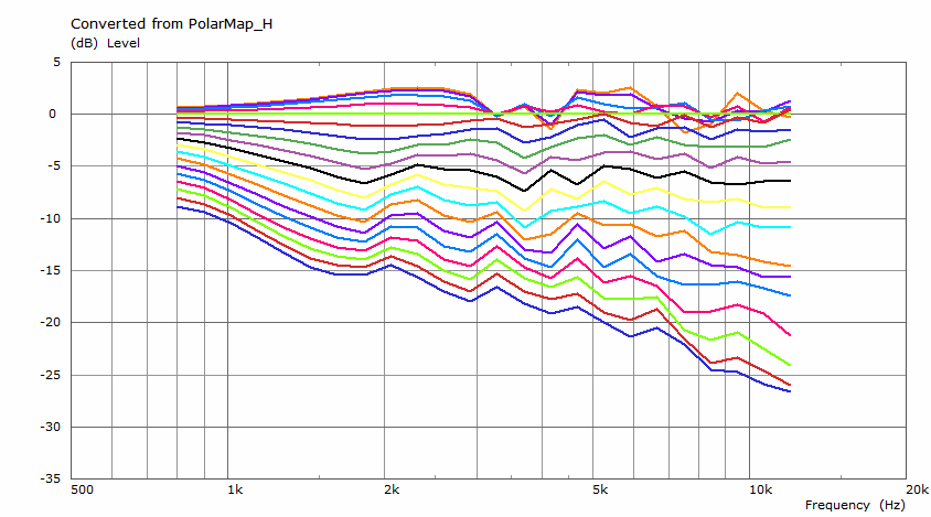
And this is the second one I compared it with. And this is noticeably worse, observable even on the impedance, which surprised me. Does anyone have an idea why?
Probably it has to do with the shape itself. The only thing I can think of is this image from the Olson's book.
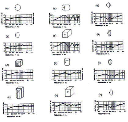
PS. I know nothing about speaker design and the math behind it, so please excuse me if it is of no relevance.
Last edited:
Shouldn't the differences be divided by the distances of the points? But I see that for a regular grid this would just scale the data.... and the velocity is the gradient (in cartesian it's the differences of the pressures.)
- BTW, wouldn't be the intensity vectors simply normal to the SPL isobars? I mean, what kind of information would such a plot show in addition to the presented SPL fields, where the pressure gradient is already visible? (The direction of particle velocity is given by the pressure gradient, isn't it?)
Last edited:
Can you make it flat for 5mm and follow up conical back to the throat? Sort of a horn shape without going all out to follow the inner horn shape. If that works, following the true horn shape would also work out (or perform even better).
That was my suggestion also 😉
I'm in no way an ABEC expert, but in Comsol the exterior field calculation boundary condition plays a role in simulating free-standing horns.
Last edited:
Shouldn't the differences be divided by the distances of the points? But I see that for a regular grid this would just scale the data.
- BTW, wouldn't be the intensity vectors simply normal to the SPL isobars? I mean, what kind of information would such a plot show in addition to the presented SPL fields, where the pressure gradient is already visible? (The direction of particle velocity is given by the pressure gradient, isn't it?)
All correct (of course), with the exception of "wouldn't the intensity vectors simply be normal to the SPL isobars?" because no they don't have to be. They would if there are no HOMs, but HOMs have velocity in the angular direction (psi, not theta) - they bounce off the walls. The normal mode would however always have the intensity normal to the coordinate surfaces.
Unfortunately I would expect to find that the difference might not be readily visible since the HOMs are generally much less than the normal mode. But that is exactly what I would want to see - if you can see them.
Does this stem from the fact that the pressures are taken as complex quantities, i.e. including phases? Because that's the only thing the SPL field doesn't show.... no they don't have to be. They would if there are no HOMs, but HOMs have velocity in the angular direction (psi, not theta) - they bounce off the walls.
Last edited:
Yes. If the phases across the wavefront are not all the same then there must be some energy moving along the wavefront.
Perhaps you could plot just this and see if the phases are constant. If they are then there are no HOMs, if not then HOMs exist. Might be a good test.
Perhaps you could plot just this and see if the phases are constant. If they are then there are no HOMs, if not then HOMs exist. Might be a good test.
The attached paper might be insightful, as well as Kolbrek's thesis: "Extensions to the Mode Matching Method for Horn Loudspeaker Simulation, Kolbrek, Bjørn, 2016."
Attachments
- Home
- Loudspeakers
- Multi-Way
- Acoustic Horn Design – The Easy Way (Ath4)