Hi all,
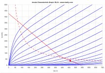
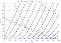
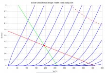
I draw the loadline for the 12AX7 and the EL34.
EL34 with 460V and Ia 38 mA at idle, Raa 4k3, g1 at -42V.
I've increased the bias voltage of the 12AX7 to 1 mA, it seems it is working in a better point. Am I right?
The gain of the EL34 is around 350 / 42 = 8,3
Feedback ratio is 47 / (39/2) = 3,4
The dynamic load of the 12ax7 is 63,8 kOhm. Seems a bit low to fully drive the El34, isn't it?
Substituing the 39k resistor with 16k like in the EL84, the load would become 93 kOhm, so the 12AX7 would work way better.
Attachments
The reason to increase the current a bit is to improve slew rate of the amp. Ian (Gingertube) talkes about it in post 607 here:
EL34 Baby Huey Amplifier
He talks about reducing R33/R34 to try to achieve 2.4ma and would like to go even a bit higher, but the existing circuit has a difficult time supporting that much current. That's why I was poking around for a better way, prompted by Ian's suggestion of using Mosfets.
gabo
Thanks for the reminder of that post. I had slipped my mind.
Hi snaper,
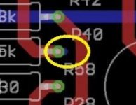
In your post 800 you have found two errors in the TENA quad amplifier, I have seen the missing connection between the resistor and the MOSFET, but I didn't understand the error in the bias layout, can you explain ?
If I am in better condition, I will correct the PCB and publish Eagle files, may be gingertube and prasi can check the schema and the PCB ?
Cheers,
Marc
Hi snaper,
In your post 800 you have found two errors in the TENA quad amplifier, I have seen the missing connection between the resistor and the MOSFET, but I didn't understand the error in the bias layout, can you explain ?
If I am in better condition, I will correct the PCB and publish Eagle files, may be gingertube and prasi can check the schema and the PCB ?
Cheers,
Marc
welcome back Marc. Glad to know you are well.
Yes, I can check the PCB for design rules and other minor things but schema needs experts eyes.
regards
prasi
Hello Prasi,
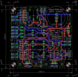
I finally recover my last PCB (my Lenovo AIO did not work anymore, but the hard disk is OK ?) and corrected the errors found by snapper 🙂
I also added a jumper to use the negative input for the feedback or a differential input version...
I am also working on some cosmetic change.
Cheers,
Marc
I finally recover my last PCB (my Lenovo AIO did not work anymore, but the hard disk is OK ?) and corrected the errors found by snapper 🙂
I also added a jumper to use the negative input for the feedback or a differential input version...
I am also working on some cosmetic change.
Cheers,
Marc
Attachments
Hello Marc,
Interesting diagram in pdf. Is this the amplifier you actually built? I didn’t read all previous pages yet (but I probably will). Do you have any measured specs?
Regards, Gerrit
Interesting diagram in pdf. Is this the amplifier you actually built? I didn’t read all previous pages yet (but I probably will). Do you have any measured specs?
Regards, Gerrit
hey all,
I'm looking to build a BH EL34 and will order boards from prasi once they are available.
I downloaded all the documentation from the start of this thread but I still have some very basic (noob) questions.
* This is a push-pull design, correct?
* Requirements for power transformer and output transformer for EL34?
For PT: Which taps are required
For OPT: Which primary impedance, power watts and DC mA
* What is the power output, per channel for EL-34 and KT-88?
Thanks!!
Bonjour Marc,I finally recover my last PCB
I just came to the forum to ask some questions about a KT88 version of the BH, and I find your (way more advanced than mine) quad KT120 design.
Starting by this post: Local feedback between grid-cathode
and GEC KT88 datasheet: https://frank.pocnet.net/sheets/086/k/KT88.pdf
and KT88 UL data: https://www.diyaudio.com/forums/att...-output-stage-local-feedback-mess011pic02-jpg
I've applied the datasheet information (B+ 560V, Raa 4k5, UL43%, PI and power mosfets supplied by +-100Vdc) with the same 27k shunt feedback resistor, for around 85W at 0,5% THD and 100W at 2% THD without global feedback.
Do you see any drawback to supply the 12ax7 PI with 560V and -100V?
Coupling caps will need to be 1kV od course, because 630V won't be enough.
I will also try Wavebourn suggestion to avoid UL and apply more shunt feedback to get (based on his experience) even better results.
I can post the LTspice file without problems if needed.
Thanks in advance
Roberto
....I downloaded all the documentation from the start of this thread but I still have some very basic (noob) questions.
I suggest you take a good look at the schematics and information in post #611. Most you your questions are answered right on the schematics. The BH EL34 PCB and power supply board is optimized for this Toroidy power transformer, which supplies all the required voltages and current.
TSTA 250/001 TOROIDY - Transformer: toroidal audio | 250VA; 115/115VAC; 275/330V; 50V; TSTA250/001 | TME - Electronic components
However, you may also use several individual transformers to provide the required voltages and currents separately or combined.
* This is a push-pull design, correct? - Yes
* Requirements for power transformer and output transformer for EL34?
For PT: Which taps are required? See the schematics. For PT you will need around 330Vac at >300ma for power, 70vac for bias for EL34, and sufficient heater current for your tubes.
For OPT: Which primary impedance, power watts and DC mA - Assuming you are actually going to use EL34 output tubes in Ultralinear configuration, you will need output transformers that reflect 4000 to 6600 Ohm plate to plate from your preferred speaker secondaries. UL taps at the usual 40-43% will be fine for EL34s.
This Toroidy output will serve you well with EL34s
TTG-EL34PP TOROIDY - Transformer: speaker | 50VA; O115x65mm; 0.008/54kHz; 200mA | TME - Electronic components
If you want to try KT88s, this output transformer will allow higher output with these tubes, while still useful with EL34
TTG-KT88PP TOROIDY - Transformer: speaker | 80VA; O115x65mm; 0.012/56kHz; 300mA | TME - Electronic components
* What is the power output, per channel for EL-34 and KT-88? At the power supply voltages the specified Toroidy transformer will provide you can expect 30-40 watts output, depending on your implementation details from a pair of EL34 output tubes.
Hope this helps!!
P.S. I have no connection with Toroidy and do not intend to specifically recommend their transformers, but they were easy to reference and served me well - there are other transformers that could serve you as well or better.
Last edited:
Hello prasi & Ian,
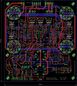
Following gingertube comments about the power supply I reversed the P MOS and made somes cosmetic modifications... If you have any suggestions, please let me know and I will try to implement them and send the Rev. 2 Gerger file to prasi if he want to produce them again ?
Rgds,
Marc
Following gingertube comments about the power supply I reversed the P MOS and made somes cosmetic modifications... If you have any suggestions, please let me know and I will try to implement them and send the Rev. 2 Gerger file to prasi if he want to produce them again ?
Rgds,
Marc
Attachments
Hello Prasi,
I finally recover my last PCB (my Lenovo AIO did not work anymore, but the hard disk is OK ?) and corrected the errors found by snapper 🙂
I also added a jumper to use the negative input for the feedback or a differential input version...
I am also working on some cosmetic change.
Cheers,
Marc
Hi Marc,
Good to know you could recover data and continue work on the pcb.
thats a very symmetrical and nice layout.
regards
prasi
Hello prasi & Ian,
Following gingertube comments about the power supply I reversed the P MOS and made somes cosmetic modifications... If you have any suggestions, please let me know and I will try to implement them and send the Rev. 2 Gerger file to prasi if he want to produce them again ?
Rgds,
Marc
Hello Marc,
I am not sure if there will be demand. If it is there, yes, I can produce.
Currently, I will have only about 5 PCBs of rev.1 remaining after considering current demands, so no problem from my side to go for rev. 2.
regards
prasi
I suggest you take a good look at the schematics and information in post #611. Most you your questions are answered right on the schematics. The BH EL34 PCB and power supply board is optimized for this Toroidy power transformer, which supplies all the required voltages and current.
TSTA 250/001 TOROIDY - Transformer: toroidal audio | 250VA; 115/115VAC; 275/330V; 50V; TSTA250/001 | TME - Electronic components
However, you may also use several individual transformers to provide the required voltages and currents separately or combined.
* This is a push-pull design, correct? - Yes
* Requirements for power transformer and output transformer for EL34?
For PT: Which taps are required? See the schematics. For PT you will need around 330Vac at >300ma for power, 70vac for bias for EL34, and sufficient heater current for your tubes.
For OPT: Which primary impedance, power watts and DC mA - Assuming you are actually going to use EL34 output tubes in Ultralinear configuration, you will need output transformers that reflect 4000 to 6600 Ohm plate to plate from your preferred speaker secondaries. UL taps at the usual 40-43% will be fine for EL34s.
This Toroidy output will serve you well with EL34s
TTG-EL34PP TOROIDY - Transformer: speaker | 50VA; O115x65mm; 0.008/54kHz; 200mA | TME - Electronic components
If you want to try KT88s, this output transformer will allow higher output with these tubes, while still useful with EL34
TTG-KT88PP TOROIDY - Transformer: speaker | 80VA; O115x65mm; 0.012/56kHz; 300mA | TME - Electronic components
* What is the power output, per channel for EL-34 and KT-88? At the power supply voltages the specified Toroidy transformer will provide you can expect 30-40 watts output, depending on your implementation details from a pair of EL34 output tubes.
Hope this helps!!
P.S. I have no connection with Toroidy and do not intend to specifically recommend their transformers, but they were easy to reference and served me well - there are other transformers that could serve you as well or better.
Hey Francois. Your reply is super helpful... I didn't realize the documents on the first post are out of date. Perhaps the ones from post #611 should be added there as well.
I'm still looking into the details, will follow up if needed.
here are a few follow up questions:
1) Amp design -- is this amp ultra-linear connection, with cathode bias?
2) OPT impedance -- I don't have any OPT's so can buy any. I prefer the Hammond 1650A series for the classic look. For EL34/KT77, should I go with 4.3K or 6.6K (1650PA or 1650NA)
3) For the choke option in the power supply PCB, how much DC rating do we need and which resistance? >300mA ?
4) Where in the schematic do you see the values... I can't seem to find it.
Thanks!
Last edited:
Hi Marc,
Been off on holidays.
Your MK2 Rev 2 power supply still has R2 way to large. try 22K in lieu of your 470K
Cheers,
Ian
Been off on holidays.
Your MK2 Rev 2 power supply still has R2 way to large. try 22K in lieu of your 470K
Cheers,
Ian
here are a few follow up questions:
1) Amp design -- is this amp ultra-linear connection, with cathode bias?
2) OPT impedance -- I don't have any OPT's so can buy any. I prefer the Hammond 1650A series for the classic look. For EL34/KT77, should I go with 4.3K or 6.6K (1650PA or 1650NA)
3) For the choke option in the power supply PCB, how much DC rating do we need and which resistance? >300mA ?
4) Where in the schematic do you see the values... I can't seem to find it.
Thanks!
Let me try to answer your questions.
1. Yes U/L, Fixed bias. But could also be wired Triode, or Pentode if you choose.
2. Same answer as with the Toroidy output transformers I referenced above. Either will work fine with EL34 or KT88, but the 4300 Ohm primary is better suited to the KT88 if you want higher power output.
3. Chokes with =>250 ma should be adequate for EL34 outputs, so Hammond 159T (2.5H, 300 ma) will be great (better than 159V). If you plan to run KT88s hard (for higher power) then 159V (1.5H, 500 ma) is probably slightly better.
4. What values are you looking for. Could you restate the question, please.
The questions you asked on the GB thread re. the DC heater supply depends on whether you plan to use the GB PCB for the power supply, or not.
Marc had recommended a DC/DC converter, which works off the two series connected 6.3V windings on the Toroidy TSTA 250/001. Go back and check where he talks about wiring the amplifier to the PS PCB.
There are too many alternatives to list if you are not using the GB PS PCB. If you don’t want to use the DC/DC converter you could get close to 6.3 Vdc if you use low forward drop rectifiers on 6.3 Vac winding with tweaked dropping resistors, (which should work fine for for the heaters) but you are unlikely to be able to regulate that. Or you could use a separate 8Vac transformer for lighting up all the tubes with regulated 6.3 Vdc. Or, With the two 6.3 Vdc in series you could readily regulate that to 12.6 Vdc, but then you will have to fiddle with the heater traces to feed the two EL34s in series.
Last edited:
Thanks again Francois.
(1) Is there a guide on the different wiring options?
(2) It took a while to get answers and I had already ordered 1650PA (6.6K) for use with EL34's. Based on the Genalex KT77 datasheet, with Fixed Bias and 400V B+ the recommended load resistance is 4.5K, so not perfect here either.
That said, most of my "8ohm" speakers dip lower to around 5-6ohm, so using a higher secondary should keep the tubes happy across the entire frequency range.
(3) I had ordered the 159V based on the recommendations in the thread.
Trying to make sense about using a choke rated for >=250mA for EL34.
Isn't each EL34 biased at 60-70mA? That alone puts us in the 240-280mA, and it doesnt include the ECC83's and other circuitry.
(4) In my first post, I asked a few questions regarding PT and OPT taps. You wrote:
Lastly, regarding the heaters...
I do plan on using the GB PCB, atleast for B+ and negative supply.
I saw the post about the DC/DC converter. It does seem like that particular unit has quite high measured noise? (I saw a video review of it on YouTube)
I don't want to go with unregulated DC or modify the PCB traces.
The options I am currently considering:
- DC/DC converter as recommended by Marc with the 2 windings in series
- 6.3V AC directly from the transformer
- Separate transformer as you mention, perhaps with something like this: Regulated DC filament supply
(1) Is there a guide on the different wiring options?
(2) It took a while to get answers and I had already ordered 1650PA (6.6K) for use with EL34's. Based on the Genalex KT77 datasheet, with Fixed Bias and 400V B+ the recommended load resistance is 4.5K, so not perfect here either.
That said, most of my "8ohm" speakers dip lower to around 5-6ohm, so using a higher secondary should keep the tubes happy across the entire frequency range.
(3) I had ordered the 159V based on the recommendations in the thread.
Trying to make sense about using a choke rated for >=250mA for EL34.
Isn't each EL34 biased at 60-70mA? That alone puts us in the 240-280mA, and it doesnt include the ECC83's and other circuitry.
(4) In my first post, I asked a few questions regarding PT and OPT taps. You wrote:
I looked back at the schematics and did not find an answer to any of those, although it is less critical now as I've found them elsewhere.I suggest you take a good look at the schematics and information in post #611.
Lastly, regarding the heaters...
I do plan on using the GB PCB, atleast for B+ and negative supply.
I saw the post about the DC/DC converter. It does seem like that particular unit has quite high measured noise? (I saw a video review of it on YouTube)
I don't want to go with unregulated DC or modify the PCB traces.
The options I am currently considering:
- DC/DC converter as recommended by Marc with the 2 windings in series
- 6.3V AC directly from the transformer
- Separate transformer as you mention, perhaps with something like this: Regulated DC filament supply
Last edited:
1. See #522 in this thread.
2. Good choice on your OT purchase and with 60w capability they will offer flexibility. Your Hammond 1650PA (6.6K) would be good for use with EL34's, KT77 or even KT88. You can read about fellow builder Bfpca’s results with 6.6k Toroidy outputs with KT88s, starting in this thread at #425.
3. The choke you bought is great, if not overkill for EL34s, but will give you the option to also use bigger tubes, like KT88s. Dyna ST70s use a single 1.75 Henries, 200ma. DC current, 62 ohms choke, and should be biased at 35 ma per tube. So greater or equal to 250 ma is actually quite generous for the BHEL34, since the frontend tubes combined requires less than 2 ma. At 400 Vdc plate to cathode voltage a NOS EL34 can take 60 ma maximum, new ones will probably red-plate at that operating point.
4. All original questions answered then?
Regarding heater supply: I doubt that noise from the DC/DC converter will be a problem in a tube heater circuit; as power supply for an amplifier circuit I would worry about noise.
I have not done it, but some builders have done the BH GB PCB with AC tube heaters and have not reported hum problems that I saw. See for example Bas Horneman’s thread on his BHEL84 build that he deemed a great success. He went to the effort of regulating B+, but not heater supply.
Good luck with your build.
P.S. Are you one of the buyers who are waiting for Prasi to start shipping PCBs again from India? If you are impatient I could lend (or sell) you the PCBs from my stash. PM me if you meed PCBs now.
Last edited:
Thanks again for your in-depth reply Francois.
Most of my original questions are pretty much answered.
I think I'll try AC heaters for simplicity and experiment with the DC/DC converter if needed.
I went through the last ~30 pages of this thread and encountered Ian's recommendations for modding the PS board and component values on the EL34 boards.
I assume those should be implemented vs. the default BOM ?
Additionally, what are people running for EL34 bias in this circuit?
- Home
- Amplifiers
- Tubes / Valves
- EL34 Baby Huey Amplifier