I have not checked but I think +12volts will likely do the job. The way the board is set up stock it takes the unregulated supply for the +12v regulator and uses that for the + bias voltage. So you could use that and if you have no issue with noise then you are good. I am just building the EL84 version with a power supply board. I am thinking of putting at least 1 board on the test bench and checking it before I assemble everything. If I do that I will see if 12v will drive the grids to 0volts. My KT88 version uses +22 regulated for the +bias.
Thanks again. My concern had been that the PS Mk2 board uses the unregulated 15V to supply the drivers; followed by a full-fledged 12 volt regulator to only supply a timer IC and relay. It seems like a waste of regulation capability NOT to use it for the drivers too, hence my question if 12Vdc (regulated) supply for the drivers would be better (than 15 Vdc (unregulated).
I believe gingertube has written that around 20Vdc would be “good” for the driver +supply, but I have not seen a lower limit of what would be acceptable, nor an optimal value. Unfortunately I’m just now learning LTSpice, so I can’t figure that out myself without trial and error.
tena pcb has a bug in the mosfets area and in the bias setting. does anyone have corrected drawing?
An other more interesting evolution will be a quad KT120 version based on a combination of the Baby Huey and the TENA schematics, I have started the project but it is on hold since I have these health problems, may be if I feel better and if Prasi and Gingertube are interested to help we can finalise this ultimate version ?
The TENA schematics and PCB design that Marc published way back was preliminary work and was put on hold as Marc says in post #746. If this is your interest you could contribute to this design.
Last edited:
I believe gingertube has written that around 20Vdc would be “good” for the driver +supply, but I have not seen a lower limit of what would be acceptable, nor an optimal value.
The above relates to the Mk2 design/PCB. I forgot to point out that in the BHEL84 and “Mk1” EL34, the +supply to the Mosfet drivers was specified as +65Vdc, with bias at -65vdc.
......why the maximum B+ is 400 V?
It is not if you are building Baby Huey with EL34 output tubes, or one of the other compatible tubes. What gave you that impression, were you perhaps thinking of the BHEL84 which should be kept under about 330Vdc?
If you used the specified 500V main capacitors in the Mk2 power supply and on the Mk2 amplifier PCBs, then you could safely go higher than 400Vdc for your B+. However, 450-460V is the practical limit that Marc (the PCB designer) mentioned earlier on in this thread. He also posted a wiring diagram for the PSU, power transformer and Amp PCB. I attached it for your convenience .
If you have a specific reason to go higher than 450V it might be possible, but since the ECC83 supply, bias supply and other elements have not been tested at this +B level, they need to carefully considered and perhaps some component values changed, so it could be a challenge to get it all right and correctly balanced.
Attachments
Last edited:
Merci Francois, my question is based on the schematic attached to the first post of the thread, which shows 400 V as a limit for the power supply.What gave you that impression, were you perhaps thinking of the BHEL84?
I've just a question when going to 460 V or higher: if we feed the PI with a signal wide enough, on one side there will be 2,25 mA while on the other 0 mA. This means that the latter will see B+ directly on his plate, because no current means no voltage drop on plate resistors, so the PI will see 460 V (plus the negative voltage to which is connected to, minus the drop at the CCS). How long will it last?
Merci Francois, my question is based on the schematic attached to the first post of the thread, which shows 400 V as a limit for the power supply.
I've just a question when going to 460 V or higher: if we feed the PI with a signal wide enough, on one side there will be 2,25 mA while on the other 0 mA. This means that the latter will see B+ directly on his plate, because no current means no voltage drop on plate resistors, so the PI will see 460 V (plus the negative voltage to which is connected to, minus the drop at the CCS). How long will it last?
Tube ratings are generally given for continuous DC conditions. Plate voltage can be much higher for AC signal conditions. Think about output tubes. They can have very high voltages at the plate when using an output transformer which is swinging hundreds of volts up during every cycle of signal at high power levels. If you are driving an el34 chances are you will not need more than +-40volts to do that job. If you were to somehow create the conditions you are suggesting, you would be well beyond any linear operating point and be producing distorted noise rather than music.
I have experimented with 450,425 and 400v on my BH with KT88s. i prefer the 400 setting. The difference in power output is not that noticeable and running a lower B+ allows you to have higher bias current and more class A power. If you only have a power transformer that gives you very high voltages, perhaps you could consider a choke input supply which would bring that down to a more moderate level. IMO even 450volts is pushing things with the old style boards. I’m not sure about the newer ones. If the circuit designer is recommending 450v as a maximum then I think you should realize that results will not be optimal if you go beyond that. The difference between 40 and 50w is barely noticeable and only at very high levels. Having more bias current at a lower B+ and more class A power will lead to better sound for 99% of your listening. A trade off to be considered?
Thank you Bfpca,
both for your suggestion on polarisation and maximum allowed voltage.
What do you think can be the maximum allowed B+ during the swing?
I would like to try bigger tubes that need more swing, but I don't have that information to set limits.
Thanks!
Roberto
both for your suggestion on polarisation and maximum allowed voltage.
What do you think can be the maximum allowed B+ during the swing?
I would like to try bigger tubes that need more swing, but I don't have that information to set limits.
Thanks!
Roberto
Thank you Bfpca,
both for your suggestion on polarisation and maximum allowed voltage.
What do you think can be the maximum allowed B+ during the swing?
I would like to try bigger tubes that need more swing, but I don't have that information to set limits.
Thanks!
Roberto
You can control the quiescent plate voltage on the 12ax7 by adjusting the current source. More current =lower plate voltage.
With KT88/6550 I was running -49v with 450v B+. I believe plate current was 55ma. KT120 would be very similar but allows higher plate currents and has lower plate resistance, so by running a lower Z output transformer it will produce more power without super high B+
Driving these big tubes puts a lot of strain on the 12ax7 even when running into a high impedance source follower. You can need over 100vp/p to drive these tubes and the limiting factor can be your - bias voltage which will never do the job at -65. A bare minimum is -130 if you want to drive 120vp/p. 140 + would be better. So if you do that you need to make sure the bypass filter caps on the - bias supply can take those voltages.
So you are in control of that voltage on 12ax7 plate. Set it at 180 and you can swing +70v before bumping into the 250v max dc value. This tube is used in a lot of guitar amps that I am sure punish it with very high peak ac voltages. You decide how far to push it.
My recommendation is to try the BH in a typical setup first to see if you like the sound and if you actually need more power.
A high power tube amp is a demanding build and the tubes are expensive, the heat is impressive and the sound may not actually be an improvement over a more typical el34 or even EL84 build. Take it form someone who has built a parallel KT88 push pull triode stereo amp that produces just 50wpc. It draws 500w continuous from the wall to do this. It weighs 120 lbs. 3 stage circuit and you need to buy 4 mp of kt88/6550 to re tube . $$$. And it doesn’t sound better than the BH!
I am currently building the EL84 version. I have a suspicion that it will should fantastic, perhaps outdoing my KT88 version for most music I listen to.
Last edited:
You can control the quiescent plate voltage on the 12ax7 by adjusting the current source. More current =lower plate voltage.
With KT88/6550 I was running -49v with 450v B+. I believe plate current was 55ma. KT120 would be very similar but allows higher plate currents and has lower plate resistance, so by running a lower Z output transformer it will produce more power without super high B+
Driving these big tubes puts a lot of strain on the 12ax7 even when running into a high impedance source follower. You can need over 100vp/p to drive these tubes and the limiting factor can be your - bias voltage which will never do the job at -65. A bare minimum is -130 if you want to drive 120vp/p. 140 + would be better. So if you do that you need to make sure the bypass filter caps on the - bias supply can take those voltages.
So you are in control of that voltage on 12ax7 plate. Set it at 180 and you can swing +70v before bumping into the 250v max dc value. This tube is used in a lot of guitar amps that I am sure punish it with very high peak ac voltages. You decide how far to push it.
My recommendation is to try the BH in a typical setup first to see if you like the sound and if you actually need more power.
A high power tube amp is a demanding build and the tubes are expensive, the heat is impressive and the sound may not actually be an improvement over a more typical el34 or even EL84 build. Take it form someone who has built a parallel KT88 push pull triode stereo amp that produces just 50wpc. It draws 500w continuous from the wall to do this. It weighs 120 lbs. 3 stage circuit and you need to buy 4 mp of kt88/6550 to re tube . $$$. And it doesn’t sound better than the BH!
I am currently building the EL84 version. I have a suspicion that it will should fantastic, perhaps outdoing my KT88 version for most music I listen to.
This is really good info Brian, and a good thought process, thanks for that.
Also note that increasing volume just 3db requires double the power! So as you go higher it's a law of diminishing returns. I get about 32 watts of clean power out of my KT88 BH.
- A 32 watt amp gives you a certain max volume.
- To raise the volume 3db you need a 64 watt amp.
- To raise the volume 6db you need a 128 watt amp.
- To raise the volume 9 db you need an 256 watt amp.
So as you go higher, adding another 3db becomes harder and harder. Doubling a 32 watt amp is doable. Doubling anything higher than that, especially with a tube amp, is a lot harder.
Probably easier to find 3db more efficient speakers!
gabo
The other side of the equation is - How much power do you actually need with your existing speakers. If you can measure the power levels you are using you may be surprised by how little power it takes for average listening levels. You may not need 100+ watts except when really wanting it super loud. For that, maybe it is better to switch in a higher power SS amp instead of running a high power tube amp all the time.
Hi guys,
thanks for the explanations. Yes, I'm aware of the need of power to double the perceived volume, and I'm also aware of the very low need of power (the old "the first watt is the most important one"), and that's why with my 98 dB/Wm Klipsch RF82 I went with the original EL84 version of the BH and I'm sure it will be (almost) never pushed to its limits.
My question is more related to understand how this concept can be scaled up and down to other tubes, to get less or more power with similar sonic results.
Hi Marc
It will be irrelevant to this topic, but I need a list of materials for the amplifier with Lm4702 std03 that you shared earlier, I can't find the values of some capacitors.
Can you help me ?

It will be irrelevant to this topic, but I need a list of materials for the amplifier with Lm4702 std03 that you shared earlier, I can't find the values of some capacitors.
Can you help me ?
Hi Marc
It will be irrelevant to this topic, but I need a list of materials for the amplifier with Lm4702 std03 that you shared earlier, I can't find the values of some capacitors.
Can you help me ?
Marc experienced medical issues and had not participated in this forum for several months, except one recent post. Perhaps you should PM him.
Hi Beycoast,
I don't have a BOM for this amplifier, but you will find one and a lot of infos on the National Semiconductor (now TI) AN1490 : http://www.ti.com/lit/an/snaa031a/snaa031a.pdf
My PCB is very close to this schema and it may help you !
I don't have a BOM for this amplifier, but you will find one and a lot of infos on the National Semiconductor (now TI) AN1490 : http://www.ti.com/lit/an/snaa031a/snaa031a.pdf
My PCB is very close to this schema and it may help you !
Hi Beycoast,
I don't have a BOM for this amplifier, but you will find one and a lot of infos on the National Semiconductor (now TI) AN1490 : http://www.ti.com/lit/an/snaa031a/snaa031a.pdf
My PCB is very close to this schema and it may help you !
Hi Marc
Actually I just couldn't find the values for c5-c6-c9-c10-c11-c12-c21-c22. I reviewed An1490 and extracted other values.
I just need help because I can't find it.
I also have excess boards. I can give it to those who want to do it for free.
- Ali
CCS for output mod
I was thinking about a way to increase the current in the output CCS section.
I don't think this is something that makes sense on the MK2 version.
However, for the MK3 version, which I've seen some notes on and/or possibly the monoblock "tena" version, maybe this is something to look at.
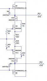
I have attached the beginnings of a schema that would replace the Q7, Q8, Q9, and Q10 and the resistors associated with them in the MK2 schema.
I didn't come up with this circuit, it's described here.
Mono and Stereo High-End Audio Magazine: DN2540 High Voltage Constant Current Source
It would be easy to tweak R33/R38 to get whatever current you wanted, the 460 ohm listed gets you about 3.1ma. This would drop right into the MK2 schema.
gabo
I was thinking about a way to increase the current in the output CCS section.
I don't think this is something that makes sense on the MK2 version.
However, for the MK3 version, which I've seen some notes on and/or possibly the monoblock "tena" version, maybe this is something to look at.
I have attached the beginnings of a schema that would replace the Q7, Q8, Q9, and Q10 and the resistors associated with them in the MK2 schema.
I didn't come up with this circuit, it's described here.
Mono and Stereo High-End Audio Magazine: DN2540 High Voltage Constant Current Source
It would be easy to tweak R33/R38 to get whatever current you wanted, the 460 ohm listed gets you about 3.1ma. This would drop right into the MK2 schema.
gabo
Attachments
Last edited:
I was thinking about a way to increase the current in the output CCS section.
Interesting! What would be the benefit of increasing the current? Lower impedance drive for the output tubes?
I have used DN2540’s before and liked the results.
That would work. IXYS makes several of these depletion mode mosfets. The DN2540, I think, has a 250v limit. Also when you start to turn up the current you end up with power dissipation that requires heatsinks, particularly inside a hot tube amp chassis. You could go to a larger one with a TO220 package to make heat sinking easier. You can get solder on heatsinks for the smaller package of the DN2540 but if you intend to use them there needs to be room between the 2540 and other components to allow for them.
That would work. IXYS makes several of these depletion mode mosfets. The DN2540, I think, has a 250v limit. Also when you start to turn up the current you end up with power dissipation that requires heatsinks, particularly inside a hot tube amp chassis. You could go to a larger one with a TO220 package to make heat sinking easier. You can get solder on heatsinks for the smaller package of the DN2540 but if you intend to use them there needs to be room between the 2540 and other components to allow for them.
Yes, there is a TO220 package and it's 400v. Where it is in the circuit, it's not exposed to anywhere near that voltage. But a heat sink would still be a reasonable idea. If you take a look, that device can handle something like 500ma, so operating it down around 3-4ma should be a breeze.
DN2540N5-G Microchip Technology | Mouser
The reason to increase the current a bit is to improve slew rate of the amp. Ian (Gingertube) talkes about it in post 607 here:
EL34 Baby Huey Amplifier
He talks about reducing R33/R34 to try to achieve 2.4ma and would like to go even a bit higher, but the existing circuit has a difficult time supporting that much current. That's why I was poking around for a better way, prompted by Ian's suggestion of using Mosfets.
gabo
Last edited:
- Home
- Amplifiers
- Tubes / Valves
- EL34 Baby Huey Amplifier