so, there´s actually no MCLK involved in the rpi´s slave mode, hmm...
The RPI's PCM interface does not use any master clock on FIFO output - it needs the bitclock to clock samples from the FIFO. LRCLK can be master or slave, depending on config. The RPI's BCM2711 peripherals documentation is quite clear about the features https://www.raspberrypi.org/documentation/hardware/raspberrypi/bcm2711/rpi_DATA_2711_1p0.pdf - page 138.
is this a special feature of the PCM5122? Because it seems very unusual that BCLK and LRCK
switch from inputs to outputs.
Actually it's quite common that pins change direction. PCM5122 does exactly that, its datasheet tells it clear too. Another setup would be a separate clock generator generating all the clocks and RPi and DAC being slaves.
No exactly, the RPi doesn't know or care about MCLK. When the RPi is master, the dac has to somehow generate it's own MCLK. Som dac chips have an embedded PLL for this, others would need an extra PLL chip.Thank alot for your effords, Henrik.
that´s a really indepth explanation.
so, there´s actually no MCLK involved in the rpi´s slave mode, hmm...
is this a special feature of the PCM5122? Because it seems very unusual that BCLK and LRCK
switch from inputs to outputs.
and it´s quite disapointing, because i won´t be able to replicate this modus with the Fifopi.
The BCLK and LRCLK can switch direction on any dac chip that is able to function as both an i2s master and slave. For example PCM5122 can, PCM5102 can't.
EDIT: too slow, phofman already answered almost the same 🙂
Hi HenrikEnquist,
I think the drawings you have made are correct.
There's no end to the details, but if the key points are the direction of BCK/LRCK/DATA, the handling of MCLKs, and the handling of PLLs, then I think it's a sufficient illustration of what we need.
For the I2S interface of RPi, a schematic diagram is provided in the BCM2836 datasheet It is. I don't know any more details than that.
Here are two example implementations of DAC masters other than the PCM5122.
Here is an example of an implementation with ES9018Q2C.
(It is controlled by a special driver)

Here is an example of the implementation in the ES9218P.
(Using a PIC microcontroller for control by the Hifiberry DAC+Pro general driver.)

I think the drawings you have made are correct.
There's no end to the details, but if the key points are the direction of BCK/LRCK/DATA, the handling of MCLKs, and the handling of PLLs, then I think it's a sufficient illustration of what we need.
For the I2S interface of RPi, a schematic diagram is provided in the BCM2836 datasheet It is. I don't know any more details than that.
Here are two example implementations of DAC masters other than the PCM5122.
Here is an example of an implementation with ES9018Q2C.
(It is controlled by a special driver)
Here is an example of the implementation in the ES9218P.
(Using a PIC microcontroller for control by the Hifiberry DAC+Pro general driver.)
Last edited:
...and the i2s lines should be as short as possible or you compromise the signals... and when the lines/cables are short, the DAC board will suffer from radiated and inductive/capacity coupled EMI from the Pi computer board. The architecture is broken to begin with.
This software adventure is like polishing the paint of a T-Ford to make it go faster for the race against a Porsche.
//
This software adventure is like polishing the paint of a T-Ford to make it go faster for the race against a Porsche.
//
...and the i2s lines should be as short as possible or you compromise the signals... and when the lines/cables are short, the DAC board will suffer from radiated and inductive/capacity coupled EMI from the Pi computer board. The architecture is broken to begin with.
This software adventure is like polishing the paint of a T-Ford to make it go faster for the race against a Porsche.
//
Which is the Porsche in this "audio adventure" ?
I checked what instruments we have at work now. It turns out I had confused two instruments, and the "spectrum analyzer" I wanted to use is actually an 8GHz vector network analyzer. It seems possible to use it as a spectrum analyzer as well, but it's quite limited compared to the real thing. Don't think it's useful to try to measure the jitter with this.
We have a proper spectrum analyzer as well but it's permanently in use so I can't borrow it.
There is also a 4 GHz, 40GS/s scope that I can use whenever I want. ot useful for precise jitter, but good enough for seeing if MASH is active or not. It should also work nicely to check how the i2s signal looks (flank steepness, amplitude etc) at the very high sample rates phofman is interested in.
No exactly, the RPi doesn't know or care about MCLK. When the RPi is master, the dac has to somehow generate it's own MCLK. Som dac chips have an embedded PLL for this, others would need an extra PLL chip.
The BCLK and LRCLK can switch direction on any dac chip that is able to function as both an i2s master and slave. For example PCM5122 can, PCM5102 can't.
EDIT: too slow, phofman already answered almost the same 🙂
Hi HenrikEnquist,
I think the drawings you have made are correct.
There's no end to the details, but if the key points are the direction of BCK/LRCK/DATA, the handling of MCLKs, and the handling of PLLs, then I think it's a sufficient illustration of what we need.
For the I2S interface of RPi, a schematic diagram is provided in the BCM2836 datasheet It is. I don't know any more details than that.
Here are two example implementations of DAC masters other than the PCM5122.
Here is an example of an implementation with ES9018Q2C.
(It is controlled by a special driver)
Here is an example of the implementation in the ES9218P.
(Using a PIC microcontroller for control by the Hifiberry DAC+Pro general driver.)
...sorry for not replying earlier, din´t have the time yesterday.
ok,ok,ok, now i understand this thing. and i know now, that i know less about modern DAC-chips
than i thought (my main interrest is in the old multbit stuff...)
thank you guys for teaching my a lesson !
i should´ve read the datasheet of the PCM5122, i´m shure it´s explained in there,
but i don´t have the time to work my way through a 120 page pdf.
I checked what instruments we have at work now. It turns out I had confused two instruments, and the "spectrum analyzer" I wanted to use is actually an 8GHz vector network analyzer. It seems possible to use it as a spectrum analyzer as well, but it's quite limited compared to the real thing. Don't think it's useful to try to measure the jitter with this.
We have a proper spectrum analyzer as well but it's permanently in use so I can't borrow it.
There is also a 4 GHz, 40GS/s scope that I can use whenever I want. ot useful for precise jitter, but good enough for seeing if MASH is active or not. It should also work nicely to check how the i2s signal looks (flank steepness, amplitude etc) at the very high sample rates phofman is interested in.
Hi Henrik,
thats good news !
i agree, a 4 Ghz Oscilloscope should be sufficent enough to show differences iin jitter.
Hi Papalius,
Here is my opinion on the measurement of sound quality using SMPD.
The measurement should concentrate on why there is a difference in sound quality. Nothing has been completely proven about the correlation between sound quality and measurements. So if there is a difference in sound quality when you listen to it, you should use your measurement to find out why the difference is there!
I think that Papalius does not have to be concerned about the measurement result excessively.
You are not publishing the SMPD for commercial purposes. Therefore you
should not be responsible for its sound quality. Also you states that in the
footer and clearly states that in the post.
The difference in sound quality between SMPD and Volumio is something everyone in Japan recognizes. Therefore, the measurement should be done in the form of clarifying why the difference in sound quality occurs.
The simple approach of solving the mystery of why the difference in sound quality between hardware and software is occurring is the right answer, not to make a superior or inferior to a specific software or specific hardware with the measurement results.
You don't have to listen to a stubborn armchair theorist.
Good luck with that.
From the Kagemusha in Japan
I made a quick test of this on my own 200MHz scope, using the hifiberry-dac overlay (and with no dac connected) and standard raspbian. Turns out none of these sample rates switch off MASH, they all switch between two different rates where the period differs by about 1.3ns. There is something fishy going on, either PLLD isn't exactly 500MHz, or it's using some other clock source.So we need a bitclock that is 64 * fs. The integer sample rates I found quickly are:
62500 = 500e6/125/64
78125 = 500e6/100/64
31250 = 500e6/250/64
There are probably more, but one is enough.
Does it use MASH to generate the 500MHz as well? Then it's hopeless..
Little more digging, using the datasheet here: https://www.raspberrypi.org/documentation/hardware/raspberrypi/bcm2711/rpi_DATA_2711_1p0.pdfI made a quick test of this on my own 200MHz scope, using the hifiberry-dac overlay (and with no dac connected) and standard raspbian. Turns out none of these sample rates switch off MASH, they all switch between two different rates where the period differs by about 1.3ns. There is something fishy going on, either PLLD isn't exactly 500MHz, or it's using some other clock source.
The PLLD_PER that's used as clock source is not 500 MHz, the actual frequency is 749999997 Hz. That's not a multiple of 64, so there is no integer sample rate that can be created without MASH.
Code:
> sudo cat /sys/kernel/debug/clk/plld_per/clk_rate
749999997
Running 44.1 kHz, 16bit:
Code:
> sudo cat /sys/kernel/debug/clk/pcm/regdump
ctl = 0x00000296
div = 0x00213768
The integer divider is 0x213 = 531 and the fractional divider is 0x768 = 1896.
Samplerate = 749999997/(531 + 1896/4096)/32 = 44099,97
The quick conclusion is that there is no point in bringing this thing to work to measure with the 4GHz scope, MASH is always active no matter what sample rate is selected. My simple 200MHz scope is already good enough to see that. An if the Pi is slave to a dac, then the jitter will be too small to measure with a 4GHz scope anyway.
I also took a quick look at the 5V and 3.3V on the expansion header. They are pretty noisy! Lots of high frequency crap there, but none of it seems to be on any frequency connected to the i2s interface. This could be redone better and I guess I could compare the noise between a standard distribution like raspbian or volumio with symphonic-mpd.
So this is inline with the idea that these processor borads are lousy companions to drive a DAC board via i2s. Seek other architectures for better (measured) performance. Move along, nothing to see here...
//
//
Henrik, thanks for the hints.
The PCM clock has two possible parents - the precise osc and the plld linux/clk-bcm2835.c at 43857965e5f526b9df807e543102a11fac1c0bcc * raspberrypi/linux * GitHub
Selection between the parents is automatic depending on the required rate - integer dividers (if possible) go first (I have not found the corresponding code in the clock driver yet). Therefore:
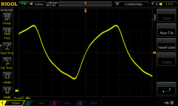
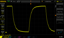
Automatically picked 54MHz crystal osc, no MASH, divider 2, bclk 27MHz. The trace is ugly, wires to my 100MHz scope are way too long. But the jitter is unnoticeable on the scope
Trace for 6MHz = 93.750kHz samplerate looks much better on the scope.
The test required trivial raising max_rate in linux/bcm2835-i2s.c at rpi-4.19.y * raspberrypi/linux * GitHub and using the same SNDRV_PCM_RATE_CONTINUOUS in linux/pcm5102a.c at e2d2941326922b63d722ebc46520c3a2287b675f * raspberrypi/linux * GitHub to allow any integer rate. The very basic I2S dtoverlay=hifiberry-dac
The PCM clock has two possible parents - the precise osc and the plld linux/clk-bcm2835.c at 43857965e5f526b9df807e543102a11fac1c0bcc * raspberrypi/linux * GitHub
Code:
cat /sys/kernel/debug/clk/pcm/clk_possible_parents
- osc - - - - plld_per -
Selection between the parents is automatic depending on the required rate - integer dividers (if possible) go first (I have not found the corresponding code in the clock driver yet). Therefore:
Code:
aplay -v -D hw:1 -c 2 -f S32_LE -r 421875 /dev/zero
Code:
cat /sys/kernel/debug/clk/pcm/clk_parent
osc
Code:
cat /sys/kernel/debug/clk/pcm/regdump
ctl = 0x00000091
div = 0x00002000
Code:
cat /proc/asound/card1/pcm0p/sub0/hw_params
access: RW_INTERLEAVED
format: S32_LE
subformat: STD
channels: 2
rate: 421875 (421875/1)
period_size: 16384
buffer_size: 65536
Automatically picked 54MHz crystal osc, no MASH, divider 2, bclk 27MHz. The trace is ugly, wires to my 100MHz scope are way too long. But the jitter is unnoticeable on the scope
Trace for 6MHz = 93.750kHz samplerate looks much better on the scope.
The test required trivial raising max_rate in linux/bcm2835-i2s.c at rpi-4.19.y * raspberrypi/linux * GitHub and using the same SNDRV_PCM_RATE_CONTINUOUS in linux/pcm5102a.c at e2d2941326922b63d722ebc46520c3a2287b675f * raspberrypi/linux * GitHub to allow any integer rate. The very basic I2S dtoverlay=hifiberry-dac
Attachments
Last edited:
symphonic-mpd v1.0.4 is available.
2020-06-24 v1.0.4 release notes
A new installation from the SD image is required.
It is not possible to update to v1.0.4 via online update.
2020-06-24 v1.0.4 release notes
- MPD port (6600) can now be enabled/disabled from the NETWORK screen of the Web UI.
- Changed parameters in aplay-rt (/etc/environment).
Changed prefetch settings and added some parameters for RoonBridge.
- Changed rc.local.
Bug fix: ympd update process at shutdown.
- added the input plugin(curl) setting in mpd.conf.
This is an additional configuration for UPnP.
- Updated the ALSA library ( libasound.so.2.0.0).
Added support for playback through RoonBridge's rtalsa/xsink driver.
- Improved the performance of rtalsa/xsink driver.
- The PLLD is set to 632217600Hz.
A new installation from the SD image is required.
It is not possible to update to v1.0.4 via online update.
Hi Papalius,
Thank you for releasing SMPD 1.04.
The sound quality has been refined more to a new level, and I think it's great. I compared it with the scratch version of HQPlayer Extendeed for linux, which runs on an Intel PC. I think the sound is now competitive enough.
In my environment, I use a Holo Spring 2 for DAC. On the Intel side, I use Matrix SpdifX-2 with DDC connection. On the RaspberryPi side, I use an IAN fifopi and connect it to the Holo Spring 2 via HDMI. They are all working perfectly.
With V1.0, most of the settings can be done using the web UI. This is a great improvement. Development is still going on, so I'm looking forward to it.
yo
2020-06-24 v1.0.4 release notes
- MPD port (6600) can now be enabled/disabled from the NETWORK screen of the Web UI.
- Changed parameters in aplay-rt (/etc/environment).
Changed prefetch settings and added some parameters for RoonBridge.
- Changed rc.local.
Bug fix: ympd update process at shutdown.
- added the input plugin(curl) setting in mpd.conf.
This is an additional configuration for UPnP.
- Updated the ALSA library ( libasound.so.2.0.0).
Added support for playback through RoonBridge's rtalsa/xsink driver.
- Improved the performance of rtalsa/xsink driver.
- The PLLD is set to 632217600Hz.
A new installation from the SD image is required.
It is not possible to update to v1.0.4 via online update.
Thank you so much, let me try
2020-06-24 v1.0.4 release notes
- MPD port (6600) can now be enabled/disabled from the NETWORK screen of the Web UI.
- Changed parameters in aplay-rt (/etc/environment).
Changed prefetch settings and added some parameters for RoonBridge.
- Changed rc.local.
Bug fix: ympd update process at shutdown.
- added the input plugin(curl) setting in mpd.conf.
This is an additional configuration for UPnP.
- Updated the ALSA library ( libasound.so.2.0.0).
Added support for playback through RoonBridge's rtalsa/xsink driver.
- Improved the performance of rtalsa/xsink driver.
- The PLLD is set to 632217600Hz.
A new installation from the SD image is required.
It is not possible to update to v1.0.4 via online update.
Hi Papalius,
so i installed the new image and it works just fine !
unfortunatly i can´t say much about the peformance (yet), because i´m in
the middle of upgrading my machine...
The button for the MPD webport in the menue is a nice addition: now it´s
easy to control MPD with an external programm.
(...allthough the programm i´ve tried before were not that great...)
Hi M_Balou,
I have to apologize to everyone using DAC slaves for an implementation error.
In symphonic-mpd, we have modified the Linux kernel source (clk-bcm2835.c ) and dt-blob.bin to adjust the PLL settings.
This was suppressing the clock swings caused by the Raspberry Pi's PLL.
Recently, looking at the source for v0.9.6 (RPi3), I've noticed a difference from the v1.0.x source.
I checked the behavior, I found that it wasn't working as expected in v1.0.x.
Soon, I will have a reversion to the v0.9.6 equivalent implementation ready to go.
This version will be delivered via online update, so no need to reinstall.
Please be patient for a while longer.
I apologize for the lack of actual testing of the DAC slave.
symphonic-mpd v1.0.5 is available.
Run the online update from the SETTINGS screen in the Web UI.
2020-06-26 v1.0.5 release notes
Here are the PLL settings for each version as a reference
v0.9.6 (RPi3)
44.1KHz : 609638400Hz (PLLA)
48KHz : 614400000Hz (PLLD)
v1.0.5 (RPi4)
44.1KHz : 632217600Hz (PLLD)
48KHz : 638976000Hz (PLLA)
Run the online update from the SETTINGS screen in the Web UI.
2020-06-26 v1.0.5 release notes
Fixed an implementation error regarding PLL settings for DAC slaves.
Here are the PLL settings for each version as a reference
v0.9.6 (RPi3)
44.1KHz : 609638400Hz (PLLA)
48KHz : 614400000Hz (PLLD)
v1.0.5 (RPi4)
44.1KHz : 632217600Hz (PLLD)
48KHz : 638976000Hz (PLLA)
- Home
- Vendor's Bazaar
- symphonic-mpd