Hi,
I just changed few outputs which were bad and tried to on the amp and it is pulling about 3.3 amps current on idle. It is getting good sinewave output. Is the current pull is normal? This Caries two transformers with a set of 5x5 mosfets on each transformer.
I just changed few outputs which were bad and tried to on the amp and it is pulling about 3.3 amps current on idle. It is getting good sinewave output. Is the current pull is normal? This Caries two transformers with a set of 5x5 mosfets on each transformer.
Did you use outputs from a reputable distributor? The IRFB31N20D is possibly the most counterfeited transistor used in car amps.
Did you replace ALL of the outputs? You can't mix them.
Did you replace ALL of the outputs? You can't mix them.
Yes all the parts are original. And changed all.Did you use outputs from a reputable distributor? The IRFB31N20D is possibly the most counterfeited transistor used in car amps.
Did you replace ALL of the outputs? You can't mix them.
Did you replace Q124 and Q125 on the driver board?
Off of the heatsink, how long does it take for the outputs to become too hot to touch?
Off of the heatsink, how long does it take for the outputs to become too hot to touch?
I did not replace them because I am having oscillations on outputs.Did you replace Q124 and Q125 on the driver board?
Off of the heatsink, how long does it take for the outputs to become too hot to touch?
High side one fet getting too hot with in 40seconds. I removed it now other fet getting hot on high side.
You can replace Q124/5 now or when they cause the amp to fail again, likely when it's within your warranty period, if you give one. The risk of the drivers causing the amp to fail catastrophically is extremely high and the cost to replace them is absolutely insignificant in comparison.
It could be that the CCS is set a bit too high but I wouldn't adjust it before replacing the drivers.
It could be that the CCS is set a bit too high but I wouldn't adjust it before replacing the drivers.
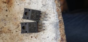
Q124 and Q125 are big transistors attaching the picture. I am trying to find if I have them in stock.You can replace Q124/5 now or when they cause the amp to fail again, likely when it's within your warranty period, if you give one. The risk of the drivers causing the amp to fail catastrophically is extremely high and the cost to replace them is absolutely insignificant in comparison.
It could be that the CCS is set a bit too high but I wouldn't adjust it before replacing the drivers.
Attachments
Those don't generally fail but they develop bad solder connections.
This is why photos are important. The few seconds they take to post can save a lot of time.
This is why photos are important. The few seconds they take to post can save a lot of time.
Sorry about that. What is CCS and how can I adjust it?Q124 and Q125 are big transistors attaching the picture. I am trying to find if I have them in stock.
Constant Current Source.
You have to increase the value (very slightly) of the resistor (R95) in series with the emitter of the CCS transistor (Q37).
The circuit board designations should be close to those for the driver board in this service manual.
http://www.bcae1.com/temp/classDtype2wdriverboardindexa998.pdf
You have to increase the value (very slightly) of the resistor (R95) in series with the emitter of the CCS transistor (Q37).
The circuit board designations should be close to those for the driver board in this service manual.
http://www.bcae1.com/temp/classDtype2wdriverboardindexa998.pdf
Constant Current Source.
You have to increase the value (very slightly) of the resistor (R95) in series with the emitter of the CCS transistor (Q37).
The circuit board designations should be close to those for the driver board in this service manual.
http://www.bcae1.com/temp/classDtype2wdriverboardindexa998.pdf
I changed it to 1k but still it doing same. I am doubting the inductors now. I am not seeing any change in colour though.
From what to 1k?
Did the idle current drop any?
Do you see a waveform that's 1/2 of the amplitude of the rail-rail oscillation at the point where the two inductors are connected?
Did the idle current drop any?
Do you see a waveform that's 1/2 of the amplitude of the rail-rail oscillation at the point where the two inductors are connected?
From what to 1k?
Did the idle current drop any?
Do you see a waveform that's 1/2 of the amplitude of the rail-rail oscillation at the point where the two inductors are connected?
I changed it from 910ohms to 1k. Attaching the waveform at the two inductor meeting point.
Still it pulling current same way. Mosfets getting hot.
Attachments

Is that 1/2 of the full waveform?
Is the ringing that bad on the FETs?
Did the idle current drop any?
Is the ringing that bad on the FETs?
Did the idle current drop any?
Is that 1/2 of the full waveform?
Is the ringing that bad on the FETs?
Did the idle current drop any?
Yes its half waveform.
I am not seeing no ringing on fets.
Idle current did not drop any.
I added another 100ohms and no difference. Still pulling around 3.2amps and high side fets getting hotTry increasing the value a bit more.
What's the DC voltage across ZD7?
Check Q37 to see if it's leaky. You'll have to pull it to check it.
Check Q37 to see if it's leaky. You'll have to pull it to check it.
5.6v across zD7.What's the DC voltage across ZD7?
Check Q37 to see if it's leaky. You'll have to pull it to check it.
Transistor pulled and is good .
- Home
- General Interest
- Car Audio
- Lanzar optidrive 2000D