While parts are again in transit, thought I'd confirm others rails are sitting expectedly at about +/-62V for the low and almost +/-97V for the high. At least some things are running well on this.
I hope I'm not lazy in asking this, but I don't recall this spelled out anywhere - are there part numbers documented anywhere for the relays? With something like relays, this would be extremely helpful.
I hope I'm not lazy in asking this, but I don't recall this spelled out anywhere - are there part numbers documented anywhere for the relays? With something like relays, this would be extremely helpful.
Not so easy to come across as many manufacturers supply relays not always with the same identity codes on them.
It is more usual to specify the type -
Solid state/mechanical.
Working voltage .
Current capacity .
Size/construction .
and so on.
China has many factories making them and importers sell them under their own logos in many cases .
It is more usual to specify the type -
Solid state/mechanical.
Working voltage .
Current capacity .
Size/construction .
and so on.
China has many factories making them and importers sell them under their own logos in many cases .
The relay I use for these is :
IMO SRKU-1CT-SL-24V DC
available from Newark.- two of the original holes in the PCB will have to be slightly enlarged (small round file or 1/16" drill), but these are drop in replacements-and work well
IMO SRKU-1CT-SL-24V DC
available from Newark.- two of the original holes in the PCB will have to be slightly enlarged (small round file or 1/16" drill), but these are drop in replacements-and work well
The relay I use for these is :
IMO SRKU-1CT-SL-24V DC
available from Newark.- two of the original holes in the PCB will have to be slightly enlarged (small round file or 1/16" drill), but these are drop in replacements-and work well
Thank you very much again!
Having parts in a cart at Mouser, I'm tempted to try this: 655-V23076A1022C133. It seems to match the one you indicated... 🙄
I'm tempted to try this: 655-V23076A1022C133. It seems to match the one you indicated... 🙄
I take that back, it's close, but not enough (pins won't match). Will keep the relays for a separate cart.
Of course, as all shippers in the US are apparently in a complete state of disarray, will not get the regulators tonight. Will report back when I do.
Last edited:
(Trying to fit this stuff between home chores and whatnot.)
Well, for one thing IC402 outputs -28.6V. I guess that's another thing that's busted. Will seek a replacement - but hasn't JRC royally messed up the pins of their positive vs. negative fixed voltage TO220 regulators? Go figure.
I can't figure this one out. With good regulators in there, the positive rail stays correct, while the negative stays incorrect (this time around -32V). I checked the new (ST Micro) AND the old negative 7918 parts and they both output correct voltages in a test fixture (including the old...). When back in circuit, they output these high negative Vs.
- R422 checks out OK
- 7918 doesn't connect the heatsink to anything.
- JP401, 402, and 403 are disconnected, so there should be no load on these rails.
- I am checking this voltage between their ground (pin 3) and output (pin 1).
I feel this is a grounding issue but not sure what/where.
Last edited:
Quote-"I feel this is a grounding issue but not sure what/where".
Without a ground reference the regulator will not work correctly so-
Check you have a "pure " ground --IE- no resistance to actual circuit ground common to the rest of the circuit .
Any resistance in that leg of the regulator will up the output voltage and that is why those types can be used at different voltages ABOVE the nominal fixed voltage of the device.
On a fixed negative regulator the "earth"/ground leg is the first one on the left with the front of the regulator facing you.
IC 79xx (7905, 7912, 7915, 7918) - Negative Voltage Regulator | TurboFuture
as @duncan2 states check the ground connection.
R422 should have the output of the bridge rectifier D403 (-35v) on one side and the output of IC402 (-18v) on the other. Check that D403 is working correctly
"7918 doesn't connect the heatsink to anything." can you post a picture?
also have C408/409 been replaced?
R422 should have the output of the bridge rectifier D403 (-35v) on one side and the output of IC402 (-18v) on the other. Check that D403 is working correctly
"7918 doesn't connect the heatsink to anything." can you post a picture?
also have C408/409 been replaced?
Quote-"I feel this is a grounding issue but not sure what/where".
Without a ground reference the regulator will not work correctly so-
Check you have a "pure " ground --IE- no resistance to actual circuit ground common to the rest of the circuit .
Any resistance in that leg of the regulator will up the output voltage and that is why those types can be used at different voltages ABOVE the nominal fixed voltage of the device.
On a fixed negative regulator the "earth"/ground leg is the first one on the left with the front of the regulator facing you.
IC 79xx (7905, 7912, 7915, 7918) - Negative Voltage Regulator | TurboFuture
Duncan - I agree, and thought of this, but on this circuit the positive and negative regulators have their ground directly connected together (pin 3 and pin 2, respectively). So why would the positive be correct and the negative elevated as it is?... Can't make sense of this. But I will triple check, and investigate the grounding of the +/-18V rails further. Maybe there's a weird resistance in the trace itself, or solder point, or something else I can't think of. But I'm thinking it must be from the part (7918) to the node carrying the ground potential to both regulators. Little can go wrong on such a short path. Or?.... 😕
R422 should have the output of the bridge rectifier D403 (-35v) on one side and the output of IC402 (-18v) on the other. Check that D403 is working correctly
The raw voltages coming in seem correct at about +/- 36V.
"7918 doesn't connect the heatsink to anything." can you post a picture?
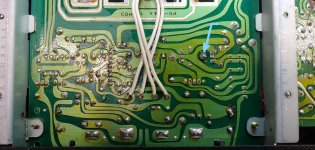
Will do. Where I was heading with this is thinking on whether - maybe - the original parts were electrically insulated from the heatsink (which on the positive side is soldered to the ground node, while on the negative is soldered to an unconnected circular pad - this is what I meant by "unconnected to anything"), and possibly when I installed my parts I ignored that. But even so, again, the 7918 doesn't connect the heatsink - and therefore the middle pin of the part, in this case INPUT - to anything, and this is the rail with issues.
Just for everyone's reference, both these parts - 7818, 7918 - connect the heatsink tab with the middle pin of the part (GND for 7818, INPUT for 7918).
also have C408/409 been replaced?
Yes, brand new caps.
"7918 doesn't connect the heatsink to anything." can you post a picture?
Enclosed. I marked up the pad that solders the 7918 HS to the board (for fastening purposes only, it seems to me).
Attachments
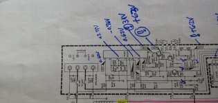
Probably unrelated, but here's some voltage measurements I've done yesterday on the protection circuitry. There's some signs of trouble around the relays and he thermal relays. Not sure though what should this read when the protection circuitry is activated vs. dormant. Through all this, the protection lights is always on.
With this specifically, maybe the relays are faulty. Not sure what types of faults have typically been seen on the relays on this thingie.
Check marks means the parts or voltages have been verified and look good.
(oopsie. sorry for the sideways pic)
With this specifically, maybe the relays are faulty. Not sure what types of faults have typically been seen on the relays on this thingie.
Check marks means the parts or voltages have been verified and look good.
(oopsie. sorry for the sideways pic)
Attachments
Last edited:
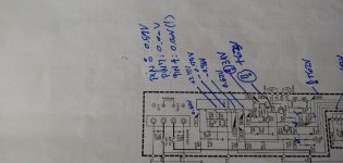
No reason to not include all pins of IC403 voltage measurements (especially pin 1). Enclosed.
On a quick side note, it seems pin 4 and 7 are at a true 0V potential, while others - such as 2 and 3, which should actually be at ground/0V, are elevated at about 0.6V... Not sure if significant in any way.
(this came again sideways... sorry. but I think it's legible ok)
On a quick side note, it seems pin 4 and 7 are at a true 0V potential, while others - such as 2 and 3, which should actually be at ground/0V, are elevated at about 0.6V... Not sure if significant in any way.
(this came again sideways... sorry. but I think it's legible ok)
Attachments
Last edited:
A bit lax of me I should have mentioned the reason the 7918 heatsink is not connected to ground is that all that range of negative voltage regulators have the steel tab connected to the "IN" and not the earth.
That,s why its shown isolated .
That,s why its shown isolated .
A bit lax of me I should have mentioned the reason the 7918 heatsink is not connected to ground is that all that range of negative voltage regulators have the steel tab connected to the "IN" and not the earth.
That,s why its shown isolated .
No worries, all that makes compete sense, and I was aware of it (from a point on). I guess the HS could have been connected to the respective pin, similarly with the positive part. But really, this was just me checking into literally everything (7918 tab isolated from HS as factory assembled?... JRC 7918s also having IN connected to tab like all others do?.. etc.), as I've ran out of more obvious options.
On further examination of this, the ground for the +/-18V supplies seems to be completely floating (which is reflected on the schematic). My checks on those rails though have typically been relative to their own ground, so they should still show +/-18V.
Mystery persists...
Last edited:
I don't like mysteries and being a very determined person I don't give up easily .
Lets get it all down in one post -
1- the 7818 regulator works just fine .
2- the 7918 regulator EARTH is connected to the 7818 earth via the copper on the PCB
3- the 7918 works okay OUT of circuit .
4-once in circuit it does not work .
5- input negative DC voltage is correct --output negative is very high.
Looking at the copper connection which is relatively short for BOTH EARTHS terminated on the same copper --using your DIGITAL meter ,NOT an analogue one put one probe on the 7818 EARTH leg ,then put the other probe on the 7918 EARTH leg .
Taking into account the resistance of the probe leads measure for ANY resistance ,it should be a dead short .
Make sure its the LEGS of both regulators on the TOP side of the PCB NOT the soldered side when you test it.
Get back Rax.
I don't like mysteries and being a very determined person I don't give up easily .
Lets get it all down in one post -
1- the 7818 regulator works just fine .
2- the 7918 regulator EARTH is connected to the 7818 earth via the copper on the PCB
3- the 7918 works okay OUT of circuit .
4-once in circuit it does not work .
5- input negative DC voltage is correct --output negative is very high.
Looking at the copper connection which is relatively short for BOTH EARTHS terminated on the same copper --using your DIGITAL meter ,NOT an analogue one put one probe on the 7818 EARTH leg ,then put the other probe on the 7918 EARTH leg .
Taking into account the resistance of the probe leads measure for ANY resistance ,it should be a dead short .
Make sure its the LEGS of both regulators on the TOP side of the PCB NOT the soldered side when you test it.
Get back Rax.
Yes, sir! Happily complying 🙂
And thank you, right on summary and I appreciate the determination - which I definitely share. Thank you for putting it to use here, for my benefit and hopefully many others, now or down the line.
On to the business at hand, I am getting virtually the same resistance with probes only - 0.15ohms - and between the earth pins (including obviously probes' resistance).
Last edited:
Well that rules out that theory ! give me a minute to think on this.
In the UK its 11.40pm so might be more than a minute.
In the UK its 11.40pm so might be more than a minute.
Well that rules out that theory ! give me a minute to think on this.
In the UK its 11.40pm so might be more than a minute.
Totally with you on this:
But I will [...] investigate the grounding of the +/-18V rails further. Maybe there's a weird resistance in the trace itself, or solder point, or something else I can't think of. But I'm thinking it must be from the part (7918) to the node carrying the ground potential to both regulators. Little can go wrong on such a short path
Ditto 🙄
I will definitely also have to sleep on this - from the vantage point of US Pacific time... very different from yours. But hope to get a bit more hands on time tonight and maybe a gremlin or two will pop.
- Home
- Amplifiers
- Solid State
- NAD 2200 repair