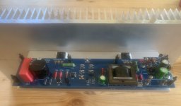
Tungsten:
Thanks for the tips on the flying leads approach to the MOSFETs. This will effectively solve the matter, it seems.
I don't plan on running excessively long leads- there are ways of orienting and otherwise positioning these sinks to enable direct correspondence with the board locations...it means the board orientation is a bit odd, but, hey, a proper enclosure hasn't been sorted yet, so, I am not too worried about the odd board orientation.
I'm going passive (cooling) with these, so there will be four such sinks in this design.
We will see how it works- while there are no published thermal resistance figures for these, the LATB experiments strongly suggest that they are more than adequate, sink per MOSFET, and actively cooled, it is clearly sufficient to use one per pair of MOSFETs.
Tungsten:
Thanks for the tips on the flying leads approach to the MOSFETs. This will effectively solve the matter, it seems.
I don't plan on running excessively long leads- there are ways of orienting and otherwise positioning these sinks to enable direct correspondence with the board locations...it means the board orientation is a bit odd, but, hey, a proper enclosure hasn't been sorted yet, so, I am not too worried about the odd board orientation.
I'm going passive (cooling) with these, so there will be four such sinks in this design.
We will see how it works- while there are no published thermal resistance figures for these, the LATB experiments strongly suggest that they are more than adequate, sink per MOSFET, and actively cooled, it is clearly sufficient to use one per pair of MOSFETs.
You should be fine passive as with one per, providing you orient them for convection. In fact, with one per you might get away without that as well. I have the fans on the lowest speed and Max is 32C.
My M2x used somewhat smaller heatsinks than the typical build around here. The chassis was basically 2.5U x 400mm deep. With the recommended 18V secondaries on the power transformer, rail voltage was initially 22.4V, given the FEP30 diodes used for rectification. When I switched to LT4320 based rectification, the rail voltage increased a little to 23.2V. Either way, bias current was a steady 1.31 Amps and the heatsinks were just warm.
What is optimum rail for Austin?
Nobody knows what the optimum (best sounding) supply voltage is, for an Austin daughter card.
To find out, I suppose you could connect a variac between the M2x and the mains, then dial the variac to adjust the mains voltage applied to the M2x transformer primary. The secondary voltage moves up and down as the primary voltage moves up and down, so with the variac you are dialling the PSU output voltage (DC) applied to the M2x as a whole ... both daughter card AND amp channel boards. If the sound changes, you don't really know whether that's because of the input stage or the power MOSFET output stage. But you could ASSUME it was 100% due to the input stage and hope you guessed right. Then find the setting of the variac which gives the best sound, measure the DC voltages on the V+ and V- bolts of the Austin, and Bob's your uncle. Then whistle past the graveyard when someone asks, what about the output stage.
Yeah, the output stage is definitely affected by the Vds across the output devices.
What I can say for sure is that I like my M2x (with Mtn View or Austin IPS) better with the slightly higher rail voltage afforded by the LT4320 synchronous rectification.
What I can say for sure is that I like my M2x (with Mtn View or Austin IPS) better with the slightly higher rail voltage afforded by the LT4320 synchronous rectification.
23.1375635VDC with a tolerance of (+/- 7.158%)
V- should be 0.642V lower of you really want to get out the micrometer.

🙂 🙂 🙂
😀 😀 😀

V- should be 0.642V lower of you really want to get out the micrometer.

🙂 🙂 🙂
😀 😀 😀

I stand corrected, it appears someone DOES know the optimum rail voltages to get the best sound from Austin.
If these numbers are accurate, and I have no reason to think otherwise, it's no surprise that the optimum V+ rail voltage is different than the optimum V- rail voltage. The PNPs and the NPNs inside Austin have different amounts of the Early Effect (LTSPICE parameter "VAF" ; giving rise to nonzero slope of Ice vs Vce in the forward active region). So for perfect balance (perhaps it's better to say "perfect SOUNDING balance") you probably do want more Vce on one than on the other.
_
Last edited:
23.1375635VDC with a tolerance of (+/- 7.158%)
1.07158 times 23.1375635 equals 24.8345469 volts.
That's how percentage tolerances work.
Listening to Austin one side of the mono, absolutely love this sound. I'll have to get the other side running, but it's going to give the Ish fits lol. Nice design that guys great work. Also listened to the Tuscon meh, I will roll some ops later on that one, but it didn't have magic with my chain the stock opamp.
THe most I can get out of this 18V secondary with the SLB is about 21.6V rails. I have some 22V secondaries but that puts me at about 26.7V, so it looks like I might need to thing about some 20v secondaries for this one. It's sounds pretty damn amazing with one speaker and 22V. 🙂
THe most I can get out of this 18V secondary with the SLB is about 21.6V rails. I have some 22V secondaries but that puts me at about 26.7V, so it looks like I might need to thing about some 20v secondaries for this one. It's sounds pretty damn amazing with one speaker and 22V. 🙂
That looks excellent!
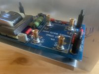
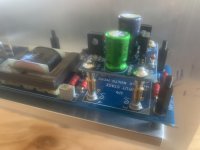
Do you have any information on the hardware attaching the daughtercard?
Do you have any information on the hardware attaching the daughtercard?
plugs
Thank you
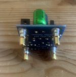
the plug connections are high-voltage contacts from Connect.
I have here the link to the German electronic distributor Reichelt. .
The contacts are used in D-Sub connectors
the soldering points fit exactly and the plugs can be soldered well.
Security Check
Security Check
kind regards
juergen
Very nice build!
Those plug and socket bits are fabulous!
I would imagine you may be fitting them together first, and then setting them in place on the main board, followed by the input board, and THEN soldering them in place?
Subsequent input boards can then be done similarly by placing the posts into the sockets, and putting the input board in place on them, and THEN soldering?
I would imagine a procedure such as this would ensure reliable fitment of all input boards to a given amp board.
Perhaps the clearances are good enough that such a procedure is not required...
Nice! I will find those somewhere on this side of the pond...
I would imagine you may be fitting them together first, and then setting them in place on the main board, followed by the input board, and THEN soldering them in place?
Subsequent input boards can then be done similarly by placing the posts into the sockets, and putting the input board in place on them, and THEN soldering?
Be careful to devise a procedure which allows either of your two Ishikawa daughter cards to fit and correctly operate in the Right amplifier channel board; AND allows either of your two Ishikawa daughter cards to fit and correctly operate in the Left amplifier channel board.
I think you probably want to avoid the situation where one of your Ishikawas is marked "LEFT CHANNEL ONLY" and the other is marked "RIGHT CHANNEL ONLY" .
I also think you probably want to avoid the situation where it's cumbersome to assemble a new pair of daughter cards nine months from now, and add them to your M2x. Hypothetically suppose that in Feb 2021, you learn that your daughter's boyfriend is an absolute Wizard at SMD soldering. So you offer to buy him 3 liters of soda and 3 large pizzas if he will please solder some (SMD!) Norwood input stage cards for you. Now must you disconnect your M2x from the audio system, haul it over to the soldering bench, and use its pegs as alignment tools to solder the mating sockets on the new Norwood boards? Ugh!
I have soldered all daughterboards with the plugs first,
and in such a way that all are the same!
there are no right or left boards, they fit everywhere!
we make an effort in the selection of the components, these resistors, this capacitor,
and do we pass our signal via a standard screw made of steel? not my thing!
and in such a way that all are the same!
there are no right or left boards, they fit everywhere!
we make an effort in the selection of the components, these resistors, this capacitor,
and do we pass our signal via a standard screw made of steel? not my thing!
US based members of diyAudio: prepare to be disappointed.
Mouser.com part numbers are
706-132C12019X
706-132C12029X
Mouser.com part numbers are
706-132C12019X
706-132C12029X
- Home
- Amplifiers
- Pass Labs
- The diyAudio First Watt M2x


