These specs are SOTA, but certainly overkill for a bass guitar preamp. Be assured you will hear no difference compared to good old TL072 except some slight increase of noise. Back on earth again I would suggest OPA2196 and the small Wima MKS capacitors.
Oh i've used TL072 in many projects before and probably never again in audio. And even then i used it cause i needed to get an opamp quickly and that one was on every corner.
It is noisy and the sound output is pretty synthetic.
Voltage is not really the best contender in OPA2196 for a battery system but thanks for the suggestion
Thanks on all the suggestions guys, really appreciate it!
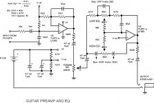
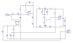
This is the schematic that i intend to use, several people made it and as they say it's pretty good. Any thoughts?
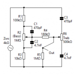
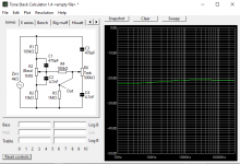
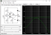
Also thinking of maybe substituting the frequency control section with the one from Tonestack, i can see it's response and looks good. Don't know what the current one is like.
This is the schematic that i intend to use, several people made it and as they say it's pretty good. Any thoughts?
Also thinking of maybe substituting the frequency control section with the one from Tonestack, i can see it's response and looks good. Don't know what the current one is like.
Attachments
If you use the first thumbnail, you might want to include an additional DC path for the second amp. Otherwise it depends entirely on the 'LOW EQ' pot, which will surely deteriorate over time. A 1 megohm resistor across the 47pF cap should do well enough without corrupting the tone function too much.
I'm glad you're planning the bi-polar power supply. Tantalum caps sound OK, but when they fail, it is usually leaky -- you could find it draining batteries faster without noticing the cause.
Maybe next time put in the prospective schematic up front.😉
Cheers
I'm glad you're planning the bi-polar power supply. Tantalum caps sound OK, but when they fail, it is usually leaky -- you could find it draining batteries faster without noticing the cause.
Maybe next time put in the prospective schematic up front.😉
Cheers
You're rightm should have posted the schematic first, didn't even think of that in the first place..
Ok, I'll try adding a resistor in parallel with 47p on the second amp. Tantalum are in the schematic already so i planned on using tantalum in the same spots, but i could use anything instead of that for audio. You think it's better to put the more audio focused like caps Silver Mica, MKP or MKS instead of tantalum?
Thanks for all the input Rick
Depends. Tantalum caps in the audio path DO have a sound (Neve consoles). You may like that coloring, or not. For reliability, tantalum caps are perhaps the worst ever made. Polypropylene are the most transparent, but only practical up to ~ 1µF; above that, bipolar Nichicon MUSE are the best.You think it's better to put the more audio focused like caps Silver Mica, MKP or MKS instead of tantalum?
Technically tantalum caps have a relatively high distortion, not nearly as bad as class 2 ceramic capacitors, but much worse than any of the other types including aluminium electrolytics. Besides, tantalum is a conflict mineral, but there are manufacturers who claim that they only use tantalum from legitimate sources and have some evidence to back that up.
If you stay with your plan to power it with dual 9V batteries, you can eliminate all 3 tantalum caps in the signal path!
If you stick with the schematic in post #22, delete the electrolytics before and after the volume pot. Then fit one from the CCW leg of the pot to ground.
Regards
If you stick with the schematic in post #22, delete the electrolytics before and after the volume pot. Then fit one from the CCW leg of the pot to ground.
Regards
Last edited:
Depends. Tantalum caps in the audio path DO have a sound (Neve consoles). You may like that coloring, or not. For reliability, tantalum caps are perhaps the worst ever made. Polypropylene are the most transparent, but only practical up to ~ 1µF; above that, bipolar Nichicon MUSE are the best.
Sums down to experimenting then, but generally i'm after transparency, thanks again !
Technically tantalum caps have a relatively high distortion, not nearly as bad as class 2 ceramic capacitors, but much worse than any of the other types including aluminium electrolytics. Besides, tantalum is a conflict mineral, but there are manufacturers who claim that they only use tantalum from legitimate sources and have some evidence to back that up.
So this also says better stay away from tantalum.. thanks bud
If you stay with your plan to power it with dual 9V batteries, you can eliminate all 3 tantalum caps in the signal path!
If you stick with the schematic in post #22, delete the electrolytics before and after the volume pot. Then fit one from the CCW leg of the pot to ground.
Regards
You mean to replace the caps with jumpers, like to literally remove them?
So you see, these are the bits i don't know, what component can be removed or replaced for a better signal and how it is related to symetrical power supply.
For changing the central freq on the bands i guess i need to play with the caps just around the pots.. ?
I'm removing the Volume pot from the schematics thou, gonna put it between the pickup and the preamp (passive Volume control) cause i'm adding passive switch mode for emergency. So i can just bypass the two tantalums and the pot altogether so i can make the PCB eve smaller! Now is at 30x30mm
But definitely thinking of making a second version of the preamp with the tone control on the second thumbnail, i've seen the response and looks pretty good.
Attachments
Last edited:
Yes. Don't fit them at all. If you're designing your own board, use that space for something else. If board is already made and the pots are to be hand wired, the CW-end of the volume control can have its wire go straight to the pad where the tantalum capacitor was.
Yes. There's a reciprocal relationship between those cap values and frequency -- double cap values, half the frequencies. If you get too creative, you may cause a gap, or an overlap in frequency response, or cause asymmetric boost/cuts.
Your 3rd paragraph and thumbnails .. Umm -- that's a tube circuit, for starters. There's no reason to use those component values in a solid-state circuit, or to tolerate the resulting response asymmetries. And I don't mean this as harsh as it sounds, but, if those FR curves look good to you -- for a bass preamp -- I'm afraid that's about all the help I can give.😉
You haven't said yet whether you're going with single supply or dual.
Regards
Yes. There's a reciprocal relationship between those cap values and frequency -- double cap values, half the frequencies. If you get too creative, you may cause a gap, or an overlap in frequency response, or cause asymmetric boost/cuts.
You'll be defeating almost every advantage of an Onboard Preamp -- I wouldn't go to the effort of building it and cutting into a perfectly good bass to install it, for the minimal benefit. A switchable *passive emergency mode* might be a sound idea if you keep the tantalums .. OR: You could design conservatively, always have a fresh pair of 9V's in your back pocket going to the gig, revel in the night and day difference in the sound of your instrument, and not look back. A friend has a Gibson Ripper with a 3rd pickup, a 3-channel preamp, and phase switches that has yet to fail -- from 1977.I'm removing the Volume pot from the schematics tho', ..
Your 3rd paragraph and thumbnails .. Umm -- that's a tube circuit, for starters. There's no reason to use those component values in a solid-state circuit, or to tolerate the resulting response asymmetries. And I don't mean this as harsh as it sounds, but, if those FR curves look good to you -- for a bass preamp -- I'm afraid that's about all the help I can give.😉
You haven't said yet whether you're going with single supply or dual.
Regards
Yes. Don't fit them at all. If you're designing your own board, use that space for something else. If board is already made and the pots are to be hand wired, the CW-end of the volume control can have its wire go straight to the pad where the tantalum capacitor was.
Yup, the board is yet to be designed so i still have time to fine tune the circuit. Ok then, i'll just leave out the tants in the line between the amps.
Yes. There's a reciprocal relationship between those cap values and frequency -- double cap values, half the frequencies. If you get too creative, you may cause a gap, or an overlap in frequency response, or cause asymmetric boost/cuts.
Good to know, thanks for this info
You'll be defeating almost every advantage of an Onboard Preamp -- I wouldn't go to the effort of building it and cutting into a perfectly good bass to install it, for the minimal benefit. A switchable *passive emergency mode* might be a sound idea if you keep the tantalums .. OR: You could design conservatively, always have a fresh pair of 9V's in your back pocket going to the gig, revel in the night and day difference in the sound of your instrument, and not look back. A friend has a Gibson Ripper with a 3rd pickup, a 3-channel preamp, and phase switches that has yet to fail -- from 1977.
I'm going for the option with Volume before the whole circuit cause i already have a bass set up that way with factory preamp that i did all the wiring and I can't complain about anything. Another thing is that you almost never play an instrument with Volume anything below 100%, it is always adjusted on the power amp. Anyway, i'll try it either way and see.
Your 3rd paragraph and thumbnails .. Umm -- that's a tube circuit, for starters. There's no reason to use those component values in a solid-state circuit, or to tolerate the resulting response asymmetries. And I don't mean this as harsh as it sounds, but, if those FR curves look good to you -- for a bass preamp -- I'm afraid that's about all the help I can give.
Sorry don't mean to be rude or anything, just want to understand this thing, how did you figure it is from a tube circuit? Also, i'm still open for any suggestions for improving the whole thing, that's just my opinion for audio visually, still not a definitive option as the circuit is still under development.
You haven't said yet whether you're going with single supply or dual.
The power supply stays the same, as the op amps i'm about to try all need symetrical V. I was just about to replace the tone section before the second amp and probably adjust the values to fit the exitisting circuit.
Thanks for all the info Rick!
By the values used. Tube amplifiers generally operate at much higher impedances than do solid state amps.....how did you figure it is from a tube circuit?
By the values used. Tube amplifiers generally operate at much higher impedances than do solid state amps.
Thanks dotneck. Then i'll adapt the values to the current and see the response
I'm going for the option with Volume before the whole circuit cause i already have a bass set up that way with factory preamp that i did all the wiring and I can't complain about anything. Another thing is that you almost never play an instrument with Volume anything below 100%, it is always adjusted on the power amp. Anyway, i'll try it either way and see.
Then the only 'preamp advantage' you've experienced is the cable driving -- useful, but only a minor part of the advantage. If you don't use the gain pot, leave it out. But realize, the signal the head sees can be much higher! You can easily set the gain of this preamp high enough to plug it directly into a HiFi/pro-PA power amp for full power out. People have; it's very clean! Most heads don't expect a signal that hot and have a high-gain amp stage first thing, which will clip. Running a passive-bass gain pot 100% is actually very smart -- anything below that and you lose higher frequencies to cable capacitance. But if it didn't change timbre (which it won't if done properly), wouldn't having a gain knob on the instrument be handy?
If you don't use the tone section in the original two-opamp circuit, you don't need that circuit OR two opamps. The biggest (but not only) problem with your tube tone circuit is, the treble control will be completely useless for bass guitar -- all you will be adjusting is finger clicks and zippers (if you play round-wounds). Please, just abandon it: It is from a long by-gone era with entirely different design objectives. The modern design goals that we take for granted -- symmetrical boost/cut and minimal interaction between pots -- are simply not achievable with that circuit. Save it for your next valve preamp design... I was just about to replace the tone section before the second amp ..
Glad to hear you're going for bi-polar supplies. It's a little more trouble, but can completely eliminate coupling capacitor coloration.
Happy building
Then the only 'preamp advantage' you've experienced is the cable driving -- useful, but only a minor part of the advantage. If you don't use the gain pot, leave it out. But realize, the signal the head sees can be much higher! You can easily set the gain of this preamp high enough to plug it directly into a HiFi/pro-PA power amp for full power out. People have; it's very clean!
All of this is true, just not that applicable to a musical instrument. Hi-Fi systems want higher output devices but the sound is very different, actually it's terrible and weirdly defined. Instrument amplifiers are very different than Hi-Fi systems.
Most heads don't expect a signal that hot and have a high-gain amp stage first thing, which will clip. Running a passive-bass gain pot 100% is actually very smart -- anything below that and you lose higher frequencies to cable capacitance. But if it didn't change timbre (which it won't if done properly), wouldn't having a gain knob on the instrument be handy?
Instrument amps actually have pretty sensitive inputs and defferent impedance, thus i don't need a lot of gain on this preamp, once adjusted according to the pickup's output level it's fixed there, unless you want to really experiment with it, but that is not that common with stringed instruments. So all of that is definitely handy, just not that much needed for an instrument. Volume pot is mainly there to calm down the highest band frequencies of the pickup and is recommended to be anywhere from 250k to 1M, depending on taste, the standard being 500k. Thanks for all the thoughts given Rick 🙂
If you don't use the tone section in the original two-opamp circuit, you don't need that circuit OR two opamps. The biggest (but not only) problem with your tube tone circuit is, the treble control will be completely useless for bass guitar -- all you will be adjusting is finger clicks and zippers (if you play round-wounds). Please, just abandon it: It is from a long by-gone era with entirely different design objectives. The modern design goals that we take for granted -- symmetrical boost/cut and minimal interaction between pots -- are simply not achievable with that circuit. Save it for your next valve preamp design.
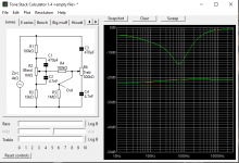
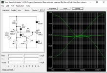
I will use the tone circuit,, actually i did some research and found that other tone circuit to be Baxandall. I implemented it in the schematic and did some component adjustment.
How does it look to you, any thoughts on the whole thing or changing something.. ? For me the visual output seems good, once i hear it i'll do additional component value adjustment if needed, but this one seems like a good candidate for the final design i think...?
Glad to hear you're going for bi-polar supplies. It's a little more trouble, but can completely eliminate coupling capacitor coloration.
Good to know why is better.
Attachments
Last edited:
Your new schematic still has issues:
- the first stage has no DC reference; the gain-setting resistors (the ones with no value indicated on the post #36 thumbnail) must return to 'signal ground' -- in this case the connection between the 4k7 resistors across the supply
- there are still 4 electrolytic capacitors affecting the sound; the whole point of using two batteries is to connect the circuit ground to the center point (one +, one -) between the batteries; today there are plenty of small MOSFETs available for near-lossless switching
- copying the component values from the tube circuit into the other topology will not perform as you expect; you DO understand that the 'B' op-amp section is an inverting, virtual-ground implementation, do you not?
- if you're absolutely determined to use the 2nd thumbnail circuit (maybe you missed my earlier note about an above-2-or-3kHz control having No Effect Whatsoever But Finger Clicks and Zippers), just buffer it with one op-amp -- you don't need the second amp
- the supply divider will consume more current than many op-amps that have been discussed here; not being very *stiff* exacts another SQ penalty
If you're reading me as a Hi Fi bloke who thinks he knows something about instrument amps, you are sadly mistaken. Sorry, but this is gonna 1/2to be It for me.
Best Regards
James Jamerson .. umm-hmm, now THAT'S a bass player ..
Last edited:
I've set the 2 gain resistors to be trim pots temporarily till i find the correct values for gain with the pickup i'll use. Good notice on the DC reference, it does exist on the original circuit, i've missed it on mine! I'll make the DC connection here.Your new schematic still has issues:
- the first stage has no DC reference; the gain-setting resistors (the ones with no value indicated on the post #36 thumbnail) must return to 'signal ground' -- in this case the connection between the 4k7 resistors across the supply
- there are still 4 electrolytic capacitors affecting the sound; the whole point of using two batteries is to connect the circuit ground to the center point (one +, one -) between the batteries; today there are plenty of small MOSFETs available for near-lossless switching
So should i just bypass the 2 electrolitics in the audio line or replace them (all 4) with something else (with what?)? Sorry i know you mentioned i can, i'm doing plenty of stuff atm so missed a few bits while working on it.
The ground gets connected when the plug is inserted which connects pins 1 and 2 in the OUT connector. It is the "power switch" for the preamp on plug insertion.
I don't know how the implement MOSFET in here and what exactly you mean...
I've actually used the values from the same tone control that is using an opamp that i've found that explains how the Baxandall tone control works... i've attached photo of that.- copying the component values from the tube circuit into the other topology will not perform as you expect;
I see that but I don't understand it... I just modified the tone control circuit a little. Sorry if you're saying something very obvious and i don't see it, it may be frustrating to you sorry, but i don't understand everything in the schematic and probably don't see some of the bits you're refereng to. So i don't know the purpose of "inverting" and "virtual ground" here...you DO understand that the 'B' op-amp section is an inverting, virtual-ground implementation, do you not?
I'm not sure i know how to do this :/- if you're absolutely determined to use the 2nd thumbnail circuit (maybe you missed my earlier note about an above-2-or-3kHz control having No Effect Whatsoever But Finger Clicks and Zippers), just buffer it with one op-amp -- you don't need the second amp
So is there a better solution for this?- the supply divider will consume more current than many op-amps that have been discussed here; not being very *stiff* exacts another SQ penalty
I don't know this, i greatly appreciate any input, you definitely know more electronics than me... that's why i came here to ask for some help to work out the circuit.If you're reading me as a Hi Fi bloke who thinks he knows something about instrument amps, you are sadly mistaken. Sorry, but this is gonna 1/2to be It for me.
No question about that! I'm just after a different, modern bass sound, bright, open and punchy.James Jamerson .. umm-hmm, now THAT'S a bass player ..
Below is the opamp version of the Baxandall tone circiut i've found
Attachments
- Home
- Live Sound
- Instruments and Amps
- Component suggestion for a preamp please