Looks much better. Just a couple little things ..
But the change to Vol pot ground is not optional.
Leaving out *proper connectors* is entirely reasonable since the unit is built-in to the instrument.
Regards
But the change to Vol pot ground is not optional.
Leaving out *proper connectors* is entirely reasonable since the unit is built-in to the instrument.
Regards
Attachments
Looks much better. Just a couple little things ..
But the change to Vol pot ground is not optional.
Leaving out *proper connectors* is entirely reasonable since the unit is built-in to the instrument.
Regards
Thanks for the suggestions Rick, i'll make those changes.
Can i ask a few questions though, i want to understand the things you changed. And a few comments:
- The Vol pot, i connected it to signal ground cause it was that way in the orignal schematic. Apparently it was tested that way working, but not sure, those were the comments from the guy that tried the original schematic.
- The components you said can be ommited, why are they there if they can be ommited, what do they do? I see in similar circuits somewhere are in the schematic and somewhere there's nothing. (just trying to understand the reason so i'll have better grasp on the circuit)
- Freq is arbitrary now, i'll experiment what i'll like the best, but yeah could be lower for treble.
Last edited:
OPA (2)145 look like a quite interesting choice - not yet available at Mouser.🙁
Yeah so far it's the best on paper considering power consumption and architecture. It's pretty new device, came out first in 2018 i think, they are announcing the dual 2145 version.
OK, sure ..
- the Vol pot -- your schematic that I put notes on, actually had it connected to *Gnd-gnd*, the most negative potential; Signal ground is the mid-point established by the TLE2426 (thanks for turning me on to that part😉).
The other issue with the way it appears to be connected -- the wiper is in a shunt-to-ground connection; passive multi-pickup guitar wiring sometimes uses that, and they have their own good reasons. 'Traditional' wiring is preferred here, where the signal is impressed on the full span of the resistance element, and the wiper acts as a 'variable tap' to select some portion of that signal.
The original schematic had coupling capacitors on both sides of the pot -- unnecessary by simply returning the CCW end to Signal ground -- but would have worked OK.
- The 100R resistors in series at the op-amp output are considered good practice, If the signal leaves the local area. Off the board, out of the box, etc, it offers some protection from static discharge or ground problems as plugs are mated/removed. It also improves stability if the op-amp has a longer cable to drive, or something else highly capacitive. Inexperienced designers often include them not realizing that they serve no purpose when simply between two adjacent op-amps. You're tight on space, right.😉
- If you do fit the 100nF in series with R5, it needs to be much bigger -- with both tone controls full CW (OK, maybe that's unlikely, but ..), it has to drive ~14,7k ohms. Make it 4,7uF or if the bass is a 5-string, even 10uF, and non-polar -- probably another size challenge.
- Also, forgot to mention in the earlier post -- the input gain, ~20dB, might be a little high, esp given the substantial boost the tone circuit is capable of. Even with the 18V supply, if you run the tone controls up (more than a few dB) and have a hot pickup, or high action, or play some slap, you may run out of headroom. You could put another resistor switchable and parallel with RG1; if its the same value as the one already there (that stays connected, regardless of switch position), would reduce stage gain by about 6 dB. That might save a valued tone setting from clipping.
Hope this helps. You're doing great .. almost there.
Cheers
Last edited:
That is defnitely helpful, very valuable info now i understand that bit, thanks a lot 🙂
Ok, i did the mod, how does it look now?
It's a 4 string bass, passive low to medium output dual MM pickup. What about the Cout cap on the output at the end? Should that one be at least 4.7uF and non-polar as well? These tend to be pretty physically large while having high ripple current.
So the Vol pot signal ground and the In-Out signal ground shouldn't be the same? Is it good this way?
I also left R5 in place cause the signal is going to leave the PCB connect to the pot, i guess that's what you meant by "leaving the local area". Also for the Vol pot it says 10k, but i already got 500k, it's a huge difference but could 500k be used onstead of 10k for Volume? Quality pots are not really cheap so if i can avoid buying another...
Attachments
A question about the voltage divider in this circuit. Can I increase the value of the two 4k7 resistors ...to get the divider to draw less current?...
It sucks less than 1mA now. The two opamps are likely to be 5mA. Not a big savings.
Follow the same thought if you use an active buffer/splitter. Is a 0.01mA (470k) divider with a 2.5mA buffer really thriftier than a 4.7k 1mA divider?
How low/high can it go? Depends what is hanging on the reference voltage. Any number of opamp "+" pins can hang on a 47k divider; do your math. However *this* plan dumps the NFB path of the first stage into the divider. That's bigger current and potentially big audio, which can then bleed into other stages via the bias voltage. A fix here is to dump that NFB path to ground with a DC-block cap, but that's another 2-bits of cost.
It sucks less than 1mA now. The two opamps are likely to be 5mA. Not a big savings.
Follow the same thought if you use an active buffer/splitter. Is a 0.01mA (470k) divider with a 2.5mA buffer really thriftier than a 4.7k 1mA divider?
These opamps are 0.45mA each, how does 5mA comes up?
How low/high can it go? Depends what is hanging on the reference voltage. Any number of opamp "+" pins can hang on a 47k divider; do your math. However *this* plan dumps the NFB path of the first stage into the divider. That's bigger current and potentially big audio, which can then bleed into other stages via the bias voltage. A fix here is to dump that NFB path to ground with a DC-block cap, but that's another 2-bits of cost.
I don't quite understand this section of the circuit, so i can do some of the math but i don't know if it will be good for this circuit. I would need to see the NFB path thing to see what you exactly mean if you could do that. Additional costs are not too big for one off PCB so adding components is space critical only but will find a way to work around that
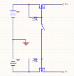
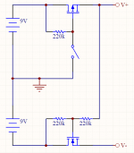
Since you use 2x9V batteries, you don't need rail splitter. If you got to use SPST on-off switch, you can use this arrangement. There is plenty of suitable MOSFETS.
Attachments
Last edited:
Since you use 2x9V batteries, you don't need rail splitter. If you got to use SPST on-off switch, you can use this arrangement. There is plenty of suitable MOSFETS.
That is an interesting solution, but requires 5 components where the rail splitter is one and is the size of one mosfet. But it's a good low power substitute. I'm space limited, and i have two big enough electrolylitics, the PCB is literally full and is SMD.
What is the switch for?
That is an interesting solution, but requires 5 components where the rail splitter is one and is the size of one mosfet. But it's a good low power substitute. I'm space limited, and i have two big enough electrolylitics, the PCB is literally full and is SMD.
What is the switch for?
It's on-off switch. When closed, mosfets become very low value resistors e.g. 0.05ohm.
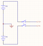
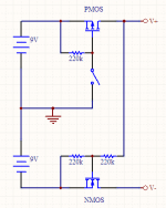
I assumed you intent to use a socket contact for switching on-off. If you are OK with dedicated DPST switch you can use this arrangement with no additional parts.
BTW there are many compact solutions suitable for the previous arrangement e.g. IRF7319-IR
Attachments
Last edited:
It's on-off switch. When closed, mosfets become very low value resistors e.g. 0.05ohm.
I assumed you intent to use a socket contact for switching on-off. If you are OK with dedicated DPST switch you can use this arrangement with no additional parts.
BTW there are many compact solutions suitable for the previous arrangement e.g. IRF7319-IR
Yes, the switch will be the stereo socket but one of the contacts is also a signal ground, so can't really use it in either of those scenarios that way. The FET power solution is interesting but probably is better fitted elsewhere. Adding a power switch isn't preferrable solution for an instrument.
Having the mid ground and the power directly from the batteries as in the second image can be unstable for the opamp if the batteries don't have equal charge or start draining unequally. Then mid ground won't be exaclty in the middle as the opamp requires and can cause instability and then can clip.
I think for this purpose the TLE is a pretty good solution, and is only one small enough component with very low power requirements. Thanks for your contribution, now i know another way how to split voltage for somewhere else where higher current is required from the power source.
Yet another arrangement, this time with one switch contact grounded.
Not realistic scenario IMHO. It's your choice anyway.
Having the mid ground and the power directly from the batteries as in the second image can be unstable for the opamp if the batteries don't have equal charge or start draining unequally. Then mid ground won't be exaclty in the middle as the opamp requires and can cause instability and then can clip.
Not realistic scenario IMHO. It's your choice anyway.
Attachments
Correction
My bad, I've mixed source and drain in the schematic. Should have double-checked first.
Here is the correct one.
My bad, I've mixed source and drain in the schematic. Should have double-checked first.
Here is the correct one.
Attachments
Last edited:
Not realistic scenario IMHO. It's your choice anyway.
Not going against you, but it's actually getting more and more realistic the more the batteries discharge. I cannot leave this to if it happens, and sometimes get unstability or clipping and sometimes everything to be fine. The additional voltage dividers are there to prevent this from happening.
It's looking pretty good to me, at least. Good work.
As to the value, 25k or even 50k would be OK. But the tone circuit it feeds can be as low as 14k7 impedance, so 500k won't do. All of the gain change would be toward the top of the control -- between 4:00 and 5:00 o'clock -- and it would interact with tone.
PRR's points in post #67 are worth giving serious consideration, but it looks like the TLE2426 is designed to avoid those pitfalls. At low frequencies it has a typical output impedance of 7,5 milliOhms, rising to about 1/10 ohm at ~4kHz. So it might be wise to include a capacitor, but it'll need to be a pair, one to each rail, and of the same value. And the value will need to be fairly small, say 0,47uF (see Figure 17, snipped from the data PDF). Since the 2426 will be providing most of the stiffness, the issue of 'capacitor coloration' should be minimal.
Then just one (or two) more thing(s) ..
The capacitor, CP - 100-220uF, across the batteries can be omitted. But somehow I completely missed the very necessary supply bypassing for each op-amp!😱 Each OPA145 needs its very own 0,1 to 0,47uF ceramic capacitor very close by; it should be the closest part to the SOT-23. Still, it probably is going to pack your board even tighter.😱
Looking good, Regards
These gain values should be OK, then. The polarized (normal) output capacitor is fine; there's really no reason to consider non-polar at this point, in this circuit.(semi-quote).. 4 string bass, low to medium output pickup ..
Yes. In fact it's the only way it can be, as a single-supply design.So the Vol pot signal ground ..
It isn't necessary, but keep it if it makes you feel better. The bit about 'non-local' is really more about 'leaving the box', in the case of separate chassis, where a connector would be mated/unmated.I also left R5 in place ..
As to the value, 25k or even 50k would be OK. But the tone circuit it feeds can be as low as 14k7 impedance, so 500k won't do. All of the gain change would be toward the top of the control -- between 4:00 and 5:00 o'clock -- and it would interact with tone.
PRR's points in post #67 are worth giving serious consideration, but it looks like the TLE2426 is designed to avoid those pitfalls. At low frequencies it has a typical output impedance of 7,5 milliOhms, rising to about 1/10 ohm at ~4kHz. So it might be wise to include a capacitor, but it'll need to be a pair, one to each rail, and of the same value. And the value will need to be fairly small, say 0,47uF (see Figure 17, snipped from the data PDF). Since the 2426 will be providing most of the stiffness, the issue of 'capacitor coloration' should be minimal.
Then just one (or two) more thing(s) ..
The capacitor, CP - 100-220uF, across the batteries can be omitted. But somehow I completely missed the very necessary supply bypassing for each op-amp!😱 Each OPA145 needs its very own 0,1 to 0,47uF ceramic capacitor very close by; it should be the closest part to the SOT-23. Still, it probably is going to pack your board even tighter.😱
Looking good, Regards
Attachments


Rick, i can't thank you enough, you've been of immense help.
Ok. Will change gain according to the pickup IF necessary.
Got it, thanks. Will leave a spot for R5 on the PCB, it's small enough, if i end up not using it at the end i'll jumper it.
The caps on the rails that i've put in for each amp, i guess they can act on this as well cause they are to connect same lines..?
I partially understand this bit from PRR in case i need to modify that, but if 2426 can handle it i would leave it as is:
"How low/high can it go? Depends what is hanging on the reference voltage. Any number of opamp "+" pins can hang on a 47k divider; do your math. However *this* plan dumps the NFB path of the first stage into the divider. That's bigger current and potentially big audio, which can then bleed into other stages via the bias voltage. A fix here is to dump that NFB path to ground with a DC-block cap, but that's another 2-bits of cost."
I know what you mean, i've seen the same in the data sheet just wasn't sure if it's applicable in all scenarios with OPA145, but likely it is. The PCB, yes it is packed enough for hand soldering, it's 25x25mm.
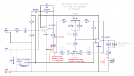
Ok, so here's updated schematic again, and the PCB layout. Two ceramic caps included for each amp, placed as close to the opamps as i could (hopefully enough room to solder, i wouldn't bake this thing 🙂). I can use 4x 470n instead of 100n since they are in parallel now and the capacitance will halve for each pair to 235nF for each rail. Seems like that should be ok.
It's looking pretty good to me, at least. Good work.
These gain values should be OK, then. The polarized (normal) output capacitor is fine; there's really no reason to consider non-polar at this point, in this circuit.
Ok. Will change gain according to the pickup IF necessary.
Yes. In fact it's the only way it can be, as a single-supply design.
It isn't necessary, but keep it if it makes you feel better. The bit about 'non-local' is really more about 'leaving the box', in the case of separate chassis, where a connector would be mated/unmated.
As to the value, 25k or even 50k would be OK. But the tone circuit it feeds can be as low as 14k7 impedance, so 500k won't do. All of the gain change would be toward the top of the control -- between 4:00 and 5:00 o'clock -- and it would interact with tone.
Got it, thanks. Will leave a spot for R5 on the PCB, it's small enough, if i end up not using it at the end i'll jumper it.
PRR's points in post #67 are worth giving serious consideration, but it looks like the TLE2426 is designed to avoid those pitfalls. At low frequencies it has a typical output impedance of 7,5 milliOhms, rising to about 1/10 ohm at ~4kHz. So it might be wise to include a capacitor, but it'll need to be a pair, one to each rail, and of the same value. And the value will need to be fairly small, say 0,47uF (see Figure 17, snipped from the data PDF). Since the 2426 will be providing most of the stiffness, the issue of 'capacitor coloration' should be minimal.
The caps on the rails that i've put in for each amp, i guess they can act on this as well cause they are to connect same lines..?
I partially understand this bit from PRR in case i need to modify that, but if 2426 can handle it i would leave it as is:
"How low/high can it go? Depends what is hanging on the reference voltage. Any number of opamp "+" pins can hang on a 47k divider; do your math. However *this* plan dumps the NFB path of the first stage into the divider. That's bigger current and potentially big audio, which can then bleed into other stages via the bias voltage. A fix here is to dump that NFB path to ground with a DC-block cap, but that's another 2-bits of cost."
Then just one (or two) more thing(s) ..
The capacitor, CP - 100-220uF, across the batteries can be omitted. But somehow I completely missed the very necessary supply bypassing for each op-amp!😱 Each OPA145 needs its very own 0,1 to 0,47uF ceramic capacitor very close by; it should be the closest part to the SOT-23. Still, it probably is going to pack your board even tighter.😱
I know what you mean, i've seen the same in the data sheet just wasn't sure if it's applicable in all scenarios with OPA145, but likely it is. The PCB, yes it is packed enough for hand soldering, it's 25x25mm.
Ok, so here's updated schematic again, and the PCB layout. Two ceramic caps included for each amp, placed as close to the opamps as i could (hopefully enough room to solder, i wouldn't bake this thing 🙂). I can use 4x 470n instead of 100n since they are in parallel now and the capacitance will halve for each pair to 235nF for each rail. Seems like that should be ok.
Attachments
-
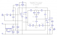 BOP ALL SMD Baxandall PeterVis & standard + Vol - final simple Rail Splitter symm V v2.png87.9 KB · Views: 81
 -
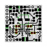 BOP ALL SMD Baxandall PeterVis & standard + Vol - final simple Rail Splitter symm V v2 PCB Front.png42.9 KB · Views: 89
 -
 BOP ALL SMD Baxandall PeterVis & standard + Vol - final simple Rail Splitter symm V v2 PCB Back.png33.7 KB · Views: 68
Correction on the previous post "capacitor value will halve in parallel" - it will double actually. Will use 4x 100n.
Congratulations.
Now that you are in the last leg of your design, 3 suggestions:
1) 10X/20dB gain in the first gain stage is too much, you will clip and have no way to control that since gain pot is after it.
Suggest you use 4X or 5X TOPS, and that because of the 18V supply.
If you had used a 9V supply, no more than 2X or 3X TOPS would be advisable.
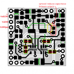
2) you connected Baxandall tone control net straight to volume pot wiper.
It is advisable to insert a cap between them (think 1 to 10uF), or your Bass control will allow almost 20dB *DC* gain for no good advantage.
Or to see it from other point of view, maximum Bass boost goes down to DC ... who wants that?
3) didn´t check PCB connectivity, but you left too little "useful" copper.
You can use WAY wider tracks almost everywhere, there is a lot of free space available.
Not for "electrical" reasons, current is nil, but mechanical ones.
And etching ones: if you etch your own boards a grain of dust, a small bubble , a small toner pinhole, a scratch or small almost invisible crack can ruin your day.
And leave a more substantial copper ring around each hole, doubly so on those receiving wires.
PCB software usually comes preset for very small pads (think 62 mil or so) and thin tracks (think 12 or 15 mil), so they can brag about how many tracks they can fit, pass tracks between IC pads, etc. ... not needed here.
I commercially make MI amplifiers and *try* to use 40 to 50 mil tracks or wider wherever possible (try to avoid necking down to less than 30 mil) and 100 mil pads, go figure.
Musical Instruments and their amplifiers tend to be carried around and bumped a lot by their very nature.
And IF you want to tweak your design later (I bet you will 🙂 ), thin copper makes for easy to damage or destroy pads and tracks, so make it robust from the beginning.
Please keep us updated with your build and treat us to a couple tasty solos or scales. 🙂
Now that you are in the last leg of your design, 3 suggestions:
1) 10X/20dB gain in the first gain stage is too much, you will clip and have no way to control that since gain pot is after it.
Suggest you use 4X or 5X TOPS, and that because of the 18V supply.
If you had used a 9V supply, no more than 2X or 3X TOPS would be advisable.
2) you connected Baxandall tone control net straight to volume pot wiper.
It is advisable to insert a cap between them (think 1 to 10uF), or your Bass control will allow almost 20dB *DC* gain for no good advantage.
Or to see it from other point of view, maximum Bass boost goes down to DC ... who wants that?
3) didn´t check PCB connectivity, but you left too little "useful" copper.
You can use WAY wider tracks almost everywhere, there is a lot of free space available.
Not for "electrical" reasons, current is nil, but mechanical ones.
And etching ones: if you etch your own boards a grain of dust, a small bubble , a small toner pinhole, a scratch or small almost invisible crack can ruin your day.
And leave a more substantial copper ring around each hole, doubly so on those receiving wires.
PCB software usually comes preset for very small pads (think 62 mil or so) and thin tracks (think 12 or 15 mil), so they can brag about how many tracks they can fit, pass tracks between IC pads, etc. ... not needed here.
I commercially make MI amplifiers and *try* to use 40 to 50 mil tracks or wider wherever possible (try to avoid necking down to less than 30 mil) and 100 mil pads, go figure.
Musical Instruments and their amplifiers tend to be carried around and bumped a lot by their very nature.
And IF you want to tweak your design later (I bet you will 🙂 ), thin copper makes for easy to damage or destroy pads and tracks, so make it robust from the beginning.
Please keep us updated with your build and treat us to a couple tasty solos or scales. 🙂
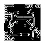
Yeah, that's a tidy piece of work -- very nice. 
Only found one oopsie-doodle. (Assuming I have the layout sorted correctly), it looks like the Vol pot ground return connects to battery Gnd, rather than the TLE2426-provided *Signal ground*. IIRC we were expecting to eliminate some power-on/off thumps and capacitor coloration w/that little trick -- since it allowed removing both coupling caps.
I'd stick with the 470n supply bypass capacitors, as long as there is room for them. They are serving double duty, after all. Also, it will keep us farther from the 'unstable' part of the graph in Fig 17 (a couple posts back -- #76 maybe).
Something else that deserves mention: The 4-capacitors in the tone circuit should be film of some sort, not ceramic. Other members know these types better than I, so best leave it to them.
I'd say, 'Go ahead and order the board', 'cause I'm pretty sure it'll work (with the Volume pot CCW connection fix). If a problem does come up, hop back on and we'll sort it out.
Generally, I'd like to see shorter traces for gain-setting dividers and virtual-ground inputs. But it certainly isn't worth setting aside your work so far.
Cheers
Attachments
Last edited:
- Home
- Live Sound
- Instruments and Amps
- Component suggestion for a preamp please