Got the parts, back to work.
Here's my toll this far:
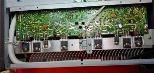
- Q313, 315, 319 failed. I got the MJWs in at this point (for good measure, also replaced known good Q317 to create a good parallel pair). As said, I further replaced Q303, 307 and 323 (failed, literally broken or suspect).
- drivers (Q309, 311) seem to be fine.
- ZD303, D311 failed. Replaced with 10V zener and 4148.
- R325, 327, 363 failed and replaced. Replaced also R323, as it looked bad though I think it measured OK.
- I didn't get to checking all other semiconductors, as things seem to go back in order as I go away from that area. Spot checked other parts and didn't find further trouble.
- started recapping the board, almost done. I've read recommendations to up C215/217 to 470uF by some testimony, but I'd like to hear some thoughts on this. My typical approach here would be to use a 100-220uF in parallel with something like 10-100nF film cap.
- on the good channel, I checked all heatsinked Qs and they are all OK.
A question for pwdiya12 - but not exclusively, of course - one step I think I need to take before firing this up 100% is to disconnect JP201/202 and leave rest alone and check voltages - have you tried this, specifically? Not 100% sure what other circuitry would be doing with this disconnected but the rest live. I guess an alternate solution to this "blowup mitigation" method is cold biasing via collectors of Q301/303 being tied together. Because the fault was so severe and I replaced all these parts, I'm a bit weary to just fire it up without more examination and health tests. But I'd probably be fine or very close to that at this point, as all power transistors are checked good or replaced. One possibility is that the protection circuitry by itself is bad - has this been seen much before? I've rain into situations before where this auxiliary circuitry goes bad to confusing and ill effects.
Here's my toll this far:
- Q313, 315, 319 failed. I got the MJWs in at this point (for good measure, also replaced known good Q317 to create a good parallel pair). As said, I further replaced Q303, 307 and 323 (failed, literally broken or suspect).
- drivers (Q309, 311) seem to be fine.
- ZD303, D311 failed. Replaced with 10V zener and 4148.
- R325, 327, 363 failed and replaced. Replaced also R323, as it looked bad though I think it measured OK.
- I didn't get to checking all other semiconductors, as things seem to go back in order as I go away from that area. Spot checked other parts and didn't find further trouble.
- started recapping the board, almost done. I've read recommendations to up C215/217 to 470uF by some testimony, but I'd like to hear some thoughts on this. My typical approach here would be to use a 100-220uF in parallel with something like 10-100nF film cap.
- on the good channel, I checked all heatsinked Qs and they are all OK.
Check the voltages from the PS- the ribbon cables can be removed, but be careful as if you insert them back the caps will still have a charge and sparks will occur.
If the overload detector is always on then check Q214 and Q338 and associated components
I have attached a slide which shows what each section is doing- try to break the diagnosis into up to Q212 and then following on from this.
A question for pwdiya12 - but not exclusively, of course - one step I think I need to take before firing this up 100% is to disconnect JP201/202 and leave rest alone and check voltages - have you tried this, specifically? Not 100% sure what other circuitry would be doing with this disconnected but the rest live. I guess an alternate solution to this "blowup mitigation" method is cold biasing via collectors of Q301/303 being tied together. Because the fault was so severe and I replaced all these parts, I'm a bit weary to just fire it up without more examination and health tests. But I'd probably be fine or very close to that at this point, as all power transistors are checked good or replaced. One possibility is that the protection circuitry by itself is bad - has this been seen much before? I've rain into situations before where this auxiliary circuitry goes bad to confusing and ill effects.
Last edited:
@rax- a couple of choices here.
1) build a dim bulb tester (lots of info here on what and how), which will tell you if the amp is drawing too much current and avoid the "magic smoke"
2) as one channel is OK you could disconnect the cable for the PS to the bad channel and then check all the voltages on the PS ( +/- 62v/+/-95v and +/18v)
3) remove both cables for both channels and test PS voltages.
In cases 2 &3 the main caps will not discharge for quite some time, so you will need to discharge them with a couple of 2W resistors (again load of info on this), before inserting them back into the amp board sockets.
I would suggest option 1 as the best. If it keeps drawing too much current then cold bias will help figure out which section (input VAS etc or output) is causing the problem. An alternative is to test the good channel to convince yourself the protection circuit is OK and then proceed to the bad channel. The protection IC can go bad/be fried as can some of the components around it- also the 18v regulators can give problems- though generally this is not the case
BTW at idle the current draw should be a stable 0.5A
Last edited:
@rax- a couple of choices here.
1) build a dim bulb tester (lots of info here on what and how), which will tell you if the amp is drawing too much current and avoid the "magic smoke"
But of course you're right and I do have one available. Given all the parts I've changed I think at this point I should be ok firing it up as is with the LBT. If I don't get any crazy draw I'm likely over the top of the hill with it, and may run it normally and check for all things for normal operation and finalize the recap.
Interestingly, my sample uses 2SA1294/2SC3263s for the "headroom switchers" (Q329/331). I believe originals should be same parts as the final amplifiers (2SA1302/2SC3281). It doesn't seem like an ulterior replacement (as in repair job), as both channels have them. Testing fine so will leave alone.
Attachments
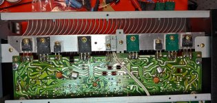
The Sanken's are retrofits by someone- they are fine replacements. What is the serial number range- (first 4 digits), and on the amp boards - what version are they?
What is the serial number range- (first 4 digits), and on the amp boards - what version are they?
Boards are MAL/R593A, and S/N is 51002401. There's also a "B" on the S/N sticker, not sure what it is.
The Sanken's are retrofits by someone- they are fine replacements.
This also tells me the hands that have been on this are more than... two. Some of the more difficult repairs I've done were those where someone else, and at times what seems to be multiple techs, have messed up and a lot of the effort was cleaning up and doing it straight forward and correctly. Not really the case with this this far, from what I can tell, at least this far.
Checked my work and turned it on this morning with LBT, and I get a dim glow out of my 75W bulb... Not sure if this is indicative of fault. I assume the half amp you mention may be enough for the glow I am seeing. For sure, the turn on inrush is far brighter and as soon as caps charge is as dull as I mention above.
But also, the lights on the front are a bit puzzling. The Protection light is on all the time. The overload light flickers in and out. I am wondering though if this happens because of the voltage drop over the light bulb and what AC voltage exactly gets delivered to the amp. I assume it may be possible the protection circuitry kicks on due to low AC voltage conditions and consequent low DC from PS. Under these conditions, I measure about 47V on the low rails and 72V on the high.
A bit of a downer, I thought the repairs on the L channel may get this running. But again, maybe all I'm seeing is the normal draw of the amp and the protection circuitry reacting to the diminished AC provided.
I'm thinking of removing one ribbon at a time (JP201, JP202) and seeing if only one of the channels turns on the protection circuitry.
- Pulling JP201 (L) makes Protection be on and Overload also be on
- Pulling JP202 (R) makes Protection be on and Overload flicker
- Pulling JP202 (R) makes Protection be on and Overload flicker
so- it is a question of isolating the issue. 1) remove the cable from JP201/2 and the connector to the input board- this way the power supply is completely isolated. As I mentioned now check all rails for correct voltages 2) check the voltages in this situation on the Protection circuit- note this down 3) connect the cable to the input board- check voltages again Now comes the tricky part- what you need to do is apply the +/- 18v rail to the main boards whilst keeping the 62v/95v isolated. To do this you will need some small connectors from the cable to the the socket on the main amp board. 4) do the right channel first (the good channel?)- check the voltages for the transistors connected to JP402.- q202/q204, q208, q212 d212/d210 etc 5) same for the left channel this should inform you regarding the input transistors (I have replaced Q201/q203 before- they need to have similar Hfe) Once this seems ok- then connect the 62v rail to the RH channel and test the components, then same on the left- then the same for the 95v rails. when you do this check the protection circuit voltages also check the 6sk20 diodes- they can fail and Q334 a good indicator of where the problem may lie is the 1.77/-1.77 at D309/D311 check q220/q214 fail as well
so- it is a question of isolating the issue. 1) remove the cable from JP201/2 and the connector to the input board- this way the power supply is completely isolated. As I mentioned now check all rails for correct voltages 2) check the voltages in this situation on the Protection circuit- note this down 3) connect the cable to the input board- check voltages again Now comes the tricky part- what you need to do is apply the +/- 18v rail to the main boards whilst keeping the 62v/95v isolated. To do this you will need some small connectors from the cable to the the socket on the main amp board. 4) do the right channel first (the good channel?)- check the voltages for the transistors connected to JP402.- q202/q204, q208, q212 d212/d210 etc 5) same for the left channel this should inform you regarding the input transistors (I have replaced Q201/q203 before- they need to have similar Hfe) Once this seems ok- then connect the 62v rail to the RH channel and test the components, then same on the left- then the same for the 95v rails. when you do this check the protection circuit voltages also check the 6sk20 diodes- they can fail and Q334 a good indicator of where the problem may lie is the 1.77/-1.77 at D309/D311 check q220/q214 fail as well
Thank you, excellent logical track there you are sketching. The +/-18V into the main boards go via their own header: JP402/403. So what I'm heading out to do is:
- disconnect JP201, JP202, JP401, JP402, JP403.
- check PS voltages and fault indicators
- reconnect JP401. Recheck +/-18V
- reconnect JP402, then 403. Check for health of input stages into main board
- reconnect JP201, then 202. See when faults get instated, at least by visual indicators.
Interesting. With all those JPs disconnected, Protection still lights on. My money's on the protection circuitry itself being faulty. Less likely, some sort of fault this circuitry is set to detect occurs even with all signal paths off.
(Trying to fit this stuff between home chores and whatnot.)
Well, for one thing IC402 outputs -28.6V. I guess that's another thing that's busted. Will seek a replacement - but hasn't JRC royally messed up the pins of their positive vs. negative fixed voltage TO220 regulators? Go figure.
Well, for one thing IC402 outputs -28.6V. I guess that's another thing that's busted. Will seek a replacement - but hasn't JRC royally messed up the pins of their positive vs. negative fixed voltage TO220 regulators? Go figure.
I seem to find MC7918 @ Mouser as a good replacement. Pin arrangement seems to fit, so maybe I haven't been paying attention to the typical configuration of pos/neg TO220 fixed voltage regulators.
the protection will stay on with all the cables disconnected from the boards- however check the voltages on the protection IC
any 7918/7818 regulators will fit- Mouser had these, replace both- also make sure you have replaced all the caps in the power supply- and the relays need replacing as well
any 7918/7818 regulators will fit- Mouser had these, replace both- also make sure you have replaced all the caps in the power supply- and the relays need replacing as well
the protection will stay on with all the cables disconnected from the boards- however check the voltages on the protection IC
any 7918/7818 regulators will fit- Mouser had these, replace both- also make sure you have replaced all the caps in the power supply- and the relays need replacing as well
Thank you, good deal. I have some 7818/7918s coming off of AMZ (quickest shipping I could get, is why) - should be in my hands tomorrow. I have a larger set of parts - main rectifier caps, may add relays, etc. - @ Mouser, but wanted to see what the negative rail repair bring to it. With a bit of luck, I can restore the low level signal stages rails tomorrow evening. Due to all this, I am assuming the input op-amps be toast though. Was planning to replace them anyway.
the input opamps should be fine, but do update them, it significantly improves the performance of the overall amp.
the relays must be done on these, they are notorious for failure
just focus on getting the power supply sorted out first
the relays must be done on these, they are notorious for failure
just focus on getting the power supply sorted out first
the input opamps should be fine
[...]
just focus on getting the power supply sorted out first
I don't think the NJM2043 can withstand that kind of voltage on the minus rail (I think it tops at -22V), which is why I assume them toast, but you're right, restoring the PS is definitely the first order of priority here.
For the input op-amps I will likely use sockets and LM4562s. It seems they do fine, even if a bit stretched with the +/-18V supplied (spec says +/-17V max).
I use LM4562 they work fine
Awesome, thanks!
Will let you know what I find out tomorrow.
- Home
- Amplifiers
- Solid State
- NAD 2200 repair