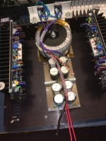
I see loads of To-3 power devices sitting on a negligible heatsink ?
😀 I was thinking the same thing. I don't think the photos can show where the true heat transfer to air happens.
The device ist bulit in 3H - the heatsinks are nearliy as high also (except at the "inlet" near the electrolytics). I've removed the air-shroud for better accessing to the mainboard. So don't worry. There are two 80mm fans forcing the air to pass around the heatsinks. It's rated at 300W/600W/1200W in 8/4/2R and at no/low load the fans are standing still. Above that they're regulated by temperature.
What topo is that amp?
There are amps that need less sizable heatsinks, like the grounded source or grounded bridge, like those from QSC or Crown for example.
All the QSC amps have heatsinks that look quite undersized, although they do force ventilate...
There are amps that need less sizable heatsinks, like the grounded source or grounded bridge, like those from QSC or Crown for example.
All the QSC amps have heatsinks that look quite undersized, although they do force ventilate...
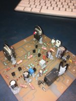
DIYAB HoneyBadger Amplifer
Just finished this today, have had alot more free time lately. It includes my custom designed protection circuit that disconnects the power from the amps with some FET's if it detects DC on the output or any overvoltage.
Just finished this today, have had alot more free time lately. It includes my custom designed protection circuit that disconnects the power from the amps with some FET's if it detects DC on the output or any overvoltage.
Attachments
-
 2020-04-26_09-31-24.JPG763.5 KB · Views: 1,493
 -
 2020-05-10_10-33-30.JPG504.8 KB · Views: 673
 -
 2020-05-09_21-50-41.jpg511.3 KB · Views: 716
 -
 2020-05-09_21-26-05.jpg416.7 KB · Views: 1,390
 -
 2020-05-09_21-25-19.JPG526 KB · Views: 1,422
 -
 2020-05-09_15-51-35.JPG538.1 KB · Views: 1,422
 -
 2020-05-04_13-00-30.JPG461.1 KB · Views: 1,484
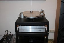
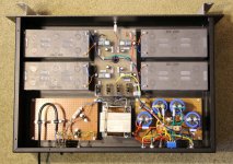
BA1200 Corona Edition in progres 😉
I do like the Corona Edition. Looks very cleaned up inside. (Sieht ja aufgeraeumt aus) 😀😀😀
Is that a Purifi woofer in the back ground?Maybe when I run it in Class A 🙂
Is that a Purifi woofer in the back ground?
Yes, that was used as the inaugaral test speaker! 😀
Very nice. Amp and speaker! How do they both sound?
And dual Flukes too... Very nice.
And dual Flukes too... Very nice.
Last edited by a moderator:
They sound great together. More on the speaker here:
Simple Passive Harsch XO Using PTT6.5 and RS28F in a Waveguide
I am in process of making a TL version but with same passive Harsch XO.
Simple Passive Harsch XO Using PTT6.5 and RS28F in a Waveguide
I am in process of making a TL version but with same passive Harsch XO.
Cast iron is a far better heat conductor than Al. Weight and shape maybe limiting factors.
Not according to this.
Best Metals for Conducting Heat
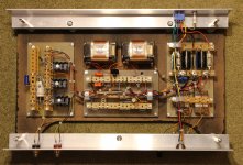
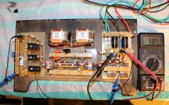
My new Phono Preamplfier
Hi there,
this is my latest moving coil phono preamplifier with an accumulator-based power supply delivering 48V in 12V increments. It comprises a high amplifying input stage with a Lundahl input transformer and low noise 2N3810 and MAT12 input transistors. The concept is a folded cascode with a differential input and a single ended output. The input stage is followed by a passive RIAA-equalization and an impedance converter at the output. The trick to achieve high gain is a choke that allows rather high idle currents on the one hand and a high impedance RIAA network at the cascoding transistor on the other hand. Output voltage is 1Veff with 0.4mV input voltage @1kHz. Maximum output voltage is 30V peak to peak.
Attachments
- Home
- Amplifiers
- Solid State
- Post your Solid State pics here