Thanks jcarr. That is great news. Great designs by Shinichi Kamijo I assume.
The "Report page" link can be translated to English and is quite readable and has a complete schematic (Fig.8) that can be downloaded as a nice PDF.
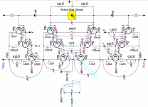
I hope it's safe to post Fig 7 for convenience since it is just a basic schematic showing the OPS topology and operating values.
The key to allow a resistor-less bipolar output stage seems to be cascoding so the inner pair cannot go into thermal runaway.
Without emitter resistors the optimum bias current for Class-AB becomes quite high, effectively determined by the parasitic resistances inside the package. With such a high optimum idle current you get Class-A for most or all of the output power range. Operation is close to square-laws.
It will be interesting to see some simulations of this circuit and/or clones there of.😉
Attachments
Still no change (I used the model from the .include statement)Hi All,
Well, a bug was in the models file, so this simulation was affected too😱.
Attached is the corrected "hegglun_hexfets-50v-ih2a-Th" file with the corrected model file. Delete the earlier file if you downloaded it. Sorry for that error.
Attachments

Elvee,
Re. schematic with Vbe multipliers - which transistors need to sense
output dev. temperature?
Would they need to be mounted directly on the output devices like Schottkys, or just on the heatsink?
Re. schematic with Vbe multipliers - which transistors need to sense
output dev. temperature?
Would they need to be mounted directly on the output devices like Schottkys, or just on the heatsink?
>So in this method, how/where these transistors should be mounted to track temperature?
>Would this work better than 4 extra Schottky diodes?
I asked, because I wonder what are pros and cons of both solutions (Elvee's Vbe multipliers vs Schottkys).
Elvee's solution, if it works, seems simpler.
It does increase distortion slightly more than Schottkys..
I need to make a few sims, to make sure that the compensation matches the tempco of the MOSFets, and the optimal way of achieving it.
As the measured tempco was a bit smaller than what I expected, your initial scheme might be sufficient.
As the measured tempco was a bit smaller than what I expected, your initial scheme might be sufficient.
Apparently, the initial circuit is already more than sufficiently overcompensated, therefore the only thing to do is to (loosely) couple Q4 and Q8 to the heatsink.
The scheme will probably have to be refined in reality, after the tests, but that's completely normal.
The scheme will probably have to be refined in reality, after the tests, but that's completely normal.
Thanks Elvee!Apparently, the initial circuit is already more than sufficiently overcompensated, therefore the only thing to do is to (loosely) couple Q4 and Q8 to the heatsink.
The scheme will probably have to be refined in reality, after the tests, but that's completely normal.
Apparently, the initial circuit is already more than sufficiently overcompensated, therefore the only thing to do is to (loosely) couple Q4 and Q8 to the heatsink.
So Q4 and Q8 fulfill the same role as Schottkys, as far as temperature compensation goes (besides of being part of CCS) ?
When you say that circuit is "sufficiently overcompensated" - it doesn't matter if it's with diodes or with Q4/Q8 sensing, right?
In both cases compensation gonna be more or less fine?
I'm planing to finalize the schematic, and start on the PCB..
Q4 and 8 compensate, whether diodes or additional components are present or not.
IMHO, the CCS alone are fine to start with.
IMHO, the CCS alone are fine to start with.
Working prototype
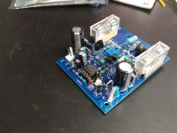
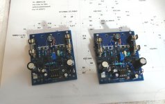
PCBs arrived 2 days ago, and today I have assembled, working and tested prototype amp (1 channel).
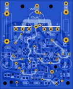
See pictures for details (attached schematic - as built, except all small transistors being all 2N, and 2 LEDs
at the op-amp, replaced with Zeners 5v1).
Idle current 300mA, rails at 42V, resistive load 8 Ohm.
All small transistors: 2N5551/2N5401, output: 1 pair of IRFPs.
opamp: TL071
Clipping at approx 78Vpp.
For the quick propotype, Q4/Q8 were NOT installed on the heatsink, so no thermal tracking was done done at all.
Amp survived all kinds of tests, including square waves for at least 30 minutes 🙂
Temporary, smaller than should be, heatsink got hot, but no too hot,
I guess no more than 50 degrees.
For square wave test, Zobel circuit has been removed.
This build will be discarded, and I'll build 2 new channels using better parts. Also gonna test it with different op-amps.
Once I have new boards done, and proper chassis/heatsink, will re-test everything, and finally, try to play music.
PCBs arrived 2 days ago, and today I have assembled, working and tested prototype amp (1 channel).
See pictures for details (attached schematic - as built, except all small transistors being all 2N, and 2 LEDs
at the op-amp, replaced with Zeners 5v1).
Idle current 300mA, rails at 42V, resistive load 8 Ohm.
All small transistors: 2N5551/2N5401, output: 1 pair of IRFPs.
opamp: TL071
Clipping at approx 78Vpp.
For the quick propotype, Q4/Q8 were NOT installed on the heatsink, so no thermal tracking was done done at all.
Amp survived all kinds of tests, including square waves for at least 30 minutes 🙂
Temporary, smaller than should be, heatsink got hot, but no too hot,
I guess no more than 50 degrees.
For square wave test, Zobel circuit has been removed.
This build will be discarded, and I'll build 2 new channels using better parts. Also gonna test it with different op-amps.
Once I have new boards done, and proper chassis/heatsink, will re-test everything, and finally, try to play music.
Attachments
-
 20200718_121819_HDR.jpg260.2 KB · Views: 181
 -
 20200718_121737_HDR.jpg290.4 KB · Views: 154
 -
 20200718_121734_HDR.jpg304.4 KB · Views: 155
 -
 20200718_121540_HDR.jpg267.7 KB · Views: 165
 -
 20200718_121507_HDR.jpg273.6 KB · Views: 172
 -
 20200718_121408_HDR.jpg223.2 KB · Views: 210
 -
 20200718_095811.jpg226.7 KB · Views: 226
 -
 hg_pcb1.jpg934.9 KB · Views: 534
 -
 schematic_as_built.jpg463.4 KB · Views: 412
Last edited:
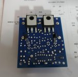
Interesting: it shows that a sufficient thermal stability is achieved without degeneration or compensation.
I wonder what the dynamic performances are (SR, ...)
I wonder what the dynamic performances are (SR, ...)
I recently purchased QA401 audio analyser, but didnt have a chance to use it yet. This gonna be the 1st amp to try it on...
Interesting: it shows that a sufficient thermal stability is achieved without degeneration or compensation.
I wonder what the dynamic performances are (SR, ...)
Output transistors are screwed to heatsink, with PCB on top of them (also held by the same screw), so pcb sits tightly right on top of the IRFPs plastic surface.
Some (small amount) heat will be transferred from transistors to the PCB, and to all other elements.
Perhaps that enough for thermal compensation, since CCS version was already over-compensated??
For the final version, I'll install Q4/Q8 under the PCB, with thermal contact to the heatsink.
To measure SR, risetime, you just need a squarewave generator and an oscilloscope (preferably analogue if you don't want to miss any subtleties of the waveform, but a good digital phosphor already works well)I recently purchased QA401 audio analyser, but didnt have a chance to use it yet. This gonna be the 1st amp to try it on...
That sounds sensible: you shouldn't push your luck too farFor the final version, I'll install Q4/Q8 under the PCB, with thermal contact to the heatsink.
Both new boards are done. Now mechanical work....
Attachments
Last edited:
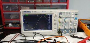
To measure SR, risetime, you just need a squarewave generator and an oscilloscope (preferably analogue if you don't want to miss any subtleties of the waveform, but a good digital phosphor already works well)
I think my sigilent oscilloscope has this function built in.
When I test next board, will play with it..
Alexander's standard.mos libraries For LTspice users. Libraries of models, examples, etc now have my/keantoken's latest VDMOS models for LT-XVII and LT-IV. More info here Better power MOSFET models in LTSpice...Alexander Bordodynov now has all my latest VDMOS models and is integrating them into his library...The LT-IV versions of all my VDMOS models will be made available by bodrodynov as a separate library file to the LT-XVII library file.
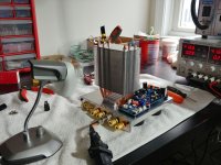
I'm testing complete amp.
Question about bias compensating.
It gets complicated because I use active cooling. Fan controller has a
thermal sensor, and it's supposed to run 'as needed' (with different speed).
The fan in the picture is only for testing, so I can control temperature easily.
Once tested, there will be fan attached to the CPU cooler.
1) Passive cooling situation:
a) start the amp
b) set idle currant to 340mA
c) as it gets hotter, idle current decreases, say to 250mA when heatsink temperature reaches 55 C. It takes 10 minutes.
I guess this shows, that thermal compensation works as it supposed to.
Not sure what will happen if amp gets even hotter..
2) Active cooling situation:
a) start the amp
b) start cooling fan
c) set idle current to 340mA
d) idle current is stable and doesn't change in time, as
temperature of the heatsink is stable, or increases just a little bit.
Am I correct in these assumptions?
I guess if active cooling is reliable, and works as designed, no thermal compensation is really needed for the amp (in most typical cases) ?
Attachments
Last edited:
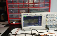
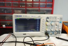
The good news is that amp played music very nicely.
I like the sound.
However it does oscillate - when no input signal present.
1) Input RCA cable connected (DAC => AMP),
but no music yet - I can see VU meters moving slightly to the right.
That was the 1st sign that something is off.
2) When I play music - everything looks and sounds good.
If I stop music - no oscillations, VU meters at 0.
3) If I disconnect input RCA cable completely - no oscillations visible on VU meters.
4) Now the bad part - if I turn the amp on WITHOUT speakers, but with input connected (and with signal present) - Zobel resistor goes in smoke.
This is totally not like it behaved on the test bench.
I tested it with/without load, with/without signal, there was no problems.
Perhaps it doesn't like long input cables? speaker cables?
Unregulated psu? Grounded heatsink?
Going back to testing/troubleshoting with signal generator and oscilloscope.
First of all, have to replace Zobel resistors (and maybe put 2W instead of 0.5W).
Last edited:
So, you ran the amp with the speakers cables connected, but without the speakers?
It is a testing situation, because a shorted or open transmission line is a stub, and can emulate any reactive impedance depending on frequency, and with a low dissipation factor.
It thus acts as an implicit, passive scanner which is going to explore all of the weaknesses of the amplifier in the frequency domain; if there is a "match", it will cause the amplifier to oscillate.
In principle, the combination of the inductive + capacitive zobel should tame any impedance, if the values are well chosen and if the amp is not on the verge of oscillation.
LTspice has lossless transmission lines models, you can try various lengths on your amp, combined with different zobel tentatives to see the effect.
In principle, you should use AC analysis, but since your problem manifests itself with peculiar startup conditions, there are probably non-linear effects kicking in, and once the AC looks OK, you should also try a transient analysis with a very short timestep, to be sure not to miss anything
- Home
- Amplifiers
- Solid State
- Square Law Amp