>So, you ran the amp with the speakers cables connected,
>but without the speakers?
No.
I see it oscillating in 2 situations:
1) right after turning on, with speakers connected, with input connected, but no input signal.
It's very weak, harmless oscillation. This is consistent, and happened every time.
If I turn on the amp WITHOUT input cables/signal, it is NOT oscillating.
2) turn on the amp on without speakers/cables connected, but with input signal.
This is very strong oscillation -burning Zobel.
Maybe there is more, but after burning Zobel, I had to stop 🙂
How I discovered it - I replaced op-amp (to lt1056) in right channel, and I wanted to listen to only one channel, so I
unplugged left speaker, and then turned on the amp (input signal connected to both channels).
Right channel (with speaker) was playing fine (so I guess lt1056 opamp works here 🙂 ), but left channel without spekaer/cables
burnt Zobel..
Last edited:
The low-level oscillation is probably a symptom of marginal stability, possibly developing into something nastier given the right conditions.
It should be ironed out.
The zobel burning could be caused by inadequate values: the 22nF looks rather small for a relatively conventional topology.
The Circlophone used 22nF, but it is not a regular, classical class AB amp.
It should be ironed out.
The zobel burning could be caused by inadequate values: the 22nF looks rather small for a relatively conventional topology.
The Circlophone used 22nF, but it is not a regular, classical class AB amp.
Check the input grounding.
Post 50 PCB shows the input ground is separate from the power ground (as it should be).
But how are these two grounds connected in your amp?
Usually there is a 10 ohm 1W on the PCB for when these grounds are not connected via the input cables.
Re speaker cable terminations
see Bob Cordell's Power amplifier book Post 9780
and
Bob Cordell's Power amplifier book Post 9788 etc
I design all my pcbs/amps like this.
Two separate grounds (dirty and input) on the pcb.
Two separate wires from PCB to the common ground point from the PSU.
Never had to use 'lifted ground' with a resistor - it's cheating 🙂
With this design, never had any hum, noise, etc...
Ground for speakers is also taken from the common ground point (from psu);
not from the pcb.
Last edited:
What you think about adding the 27pF + 100pF caps?
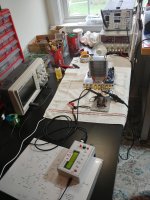
The psu, all the cables, speakers, speaker protection ,etc... are alll
the same I always use for all my other amps.
I just unplugged my current 'daily' amp - Elvee's 'current dump' amp:
EZ-Dump: dump your current without really trying
, and plugged in, in exactly the same way as literally dozens of of my other amps, the newly built amp.
Here is similar PCB (with two grounds) I made for this amp:
https://www.diyaudio.com/forums/solid-state/263065-ez-dump-dump-current-trying-12.html#post6245399
So I do not suspect anything wrong with my setup outside of the new amp.
It worked fine with dozens of other amps I built.
See the big PSU with VU meters, and square law amp on top of it.
Attachments

Last edited:
So the input common ground(s) run some distance to the PSU ground?Two separate wires from PCB to the common ground point from the PSU.
Is the input ground twisted with the power ground? There may be inductive coupling effects in the grounding.
Backing up to bench tests seems a good move. I assume that's with a regulated PSU. And I assume 1 channel at a time (ie the chanel the Zobel burned).This is totally not like it behaved on the test bench.
I tested it with/without load, with/without signal, there was no problems.
Perhaps it doesn't like long input cables? speaker cables?
Unregulated psu? Grounded heatsink?
Going back to testing/troubleshoting with signal generator and oscilloscope.
First of all, have to replace Zobel resistors (and maybe put 2W instead of 0.5W).
Yes, a 2W Zobel is what I usually use in case this happens.
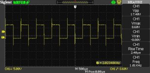
On the bench repeat the squarewave test. The bottom line appears to be noisy (below) but the top line thin, or is that just the scope's DSO resolution.
One way to check is there is some MHz oscillation is to place the 2nd scope input to the Zobel resistor which needs one end to ground (as seen on your PCB photo in Post 50, but not as shown on your circuit). If there is a MHz oscillation then the voltage across this resistor will be in the several volts region. You can trigger on Ch1 with a squarewave as before.
If there is some MHz oscillation, even low level, then try your ideas with capacitors to see which ones reduce or eliminate it. Look at the effect on risetime and overshoot or overdamping. Some values may make it worse. It is helpful to see what does what.
If there is no MHz oscillation then it is still helpful to try your ideas with capacitors to see which ones reduce or eliminate it or the effect on risetime and overshoot or overdamping. Some values may make it oscillate eg too much C6 across R7 feedbcak resistor will probably cause oscillation.
There may also be an opamp PS decoulpling issue. A 100nF capacitor is usually recommended across the PS pins of an opamp close to the opamp. In your case to try it under the PCB. Do this after some initial tests without it to see if it helps. You may need to try different opamps as a higher BW opamps need decoupling more than a lower BW one.
Next, while on the bench, can you play music with a speaker connected? Maybe one channel with a regulated PSU. This will show whether the PSU wiring has anything to do with oscillating. Or is it the input cables or speaker cables?
If there's no oscilltation this way then return to the big PSU.
All the best.
Attachments
To measure SR, risetime, you just need a squarewave generator and an oscilloscope (preferably analogue if you don't want to miss any subtleties of the waveform, but a good digital phosphor already works well)
While I'm testing again, I measured SR: 800ns - 1us while Vpp is 8V.
Once amp is stable will try higher Vpp...
My oscilloscope has option to calculate and display it.
So the input common ground(s) run some distance to the PSU ground?
Is the input ground twisted with the power ground? There may be inductive coupling effects in the grounding.
Backing up to bench tests seems a good move. I assume that's with a regulated PSU. And I assume 1 channel at a time (ie the chanel the Zobel burned).
Yes, a 2W Zobel is what I usually use in case this happens.
(...)
Thanks Ian.
>So the input common ground(s) run some distance to the PSU ground?
Common ground is one point on the aluminum chassis. So it's like 10cm wires to pcb.
Now the chassis has power plug, conneced to the big PSU.
50cm twisted wires.
>Is the input ground twisted with the power ground?
No. Cables are as far from each other as they possibly could on such small chassis.
>On the bench repeat the squarewave test. The bottom line appears to be noisy.
They always look like this, even if I connect oscilloscope directly to the generator...
>Another option might be little Zobel networks (47 Ohm + 220pF) between Gate and drain of IRFPs
What do you think about the above?
This would the easiest thing to do - it can be soldered on the top of PCB...
===============
Testing again. Replaced Zobel resistor with 10 Ohm 2W.
So far everything normal on the bench.
Without input signal (input grounded on the pcb connector) ,
I see some noise at very low level, various kHz range frequencies, averaging +- 20mV.
With input signal present, all waves showing up fine and clean.
One thing I noticed (took me a while): if I use low quality usb psu required by my wave generator, the waves I see are ugly..
Had to change the usb psu to a better (?) one.
This thing (usb charger from LG phone) was polluting...
Next step - will try real speaker and music source.
Music plays fine, no oscillations or anomalies I can see.
Now I tried small caps:
1) With both caps (27pF across feedback resistor, and 100pF across op-amp)
the amp goes crazy. Lots of oscillations all over the screen.
2) With only one cap (100pF across op-amp) - it works fine until Vpp=16V,
when is start clipping lower half.
Actually it's not just clipping, but cutting 3/4 of the bottom half of the sinus.
According the sim, cap across feedback resistor only make sense if the other cap across op-amp is present, otherwise even sim oscillates; so I haven't tried that combination.
Next thing to try: small Zobels between G and D.
If they don't hurt, will leave them, and try the whole amp again with unregulated psu.
Did you try a more aggressive zobel? A common source OP has a large unloaded gain, and it is essential to control that gain in the absence of a proper load.
4.7R/220nF should be more "normal" than your present values.
A local feedback between D and G of the OP's could also help: a series RC of a few hundreds ohm + a few nF for example.
The correct values can be found by trial and error, and you should start with large R and large C (even in the tens of nF), and decrease progressively until problems begin to appear.
With a sufficiently large C and low R, you are probably sure to kill the instabilty, but you will also kill the performance (the series R is essential to add a zero and not interfere with the GNFB loop; the MOSfets have an intrinsic feedback capacitance, which has no series resistance and can interfere with the GNFB. With an additional RC, the effect of this pole can be reduced to insignificance).
It is probably possible to find an acceptable tradeoff, good stability + good loop gain and SR
Last edited:
I tried Zobels (47 Ohm + 220pF) between DG, but this triggered immediate oscillations.
I tried them in the past on several mosfet amps, but I don't recall these Zobels to make things WORSE...
Now I see certain (random?) pattern 🙂
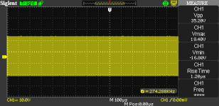
On the bench:
1) without load, all waves look good, I don't really see any problems.
Schematic 'as built', without any additions/'improvements'
2) with speaker and music, all seems to work OK. Haven't tried real loud music, so that means nothing...
3) with resistive load 8 Ohm, SOMETIMES it will start behaving weird
at over 20 Vpp at the output. Sometimes at 20Vpp, sometimes higher.
Suddenly it will draw more current (20% jump), bottom half of the sinus will be
cut almost completely, and showing messy horizontal line instead.
This happens only sometimes (3 times out of 5) and only under the load.
Sometimes amp will "latch" in this mode, and even turning off the input signal will not help it to recover.
So all in all, I think there are more than one problem.
Up to 20Vpp everything always work fine..
My original Zobel in first post was 10 Ohm/100nF.
When I upgraded resistor to 10 Ohm, 2W, it's not burning or running hot.
All oscillations seem to be non-destructive.
My lab PSU (the fan) makes funny noises when current
draw increases, to it's easy to tell when something goes wrong
and I'm able to quickly turn off the psu 🙂
This, plus current limiter, helped not to burn anything yet..
I can try more aggressive Zobel, but I think that's not the point.
There shouldn't be any oscillations, Zobel or not.
It's only for emergencies, right?
I tried them in the past on several mosfet amps, but I don't recall these Zobels to make things WORSE...
Now I see certain (random?) pattern 🙂
On the bench:
1) without load, all waves look good, I don't really see any problems.
Schematic 'as built', without any additions/'improvements'
2) with speaker and music, all seems to work OK. Haven't tried real loud music, so that means nothing...
3) with resistive load 8 Ohm, SOMETIMES it will start behaving weird
at over 20 Vpp at the output. Sometimes at 20Vpp, sometimes higher.
Suddenly it will draw more current (20% jump), bottom half of the sinus will be
cut almost completely, and showing messy horizontal line instead.
This happens only sometimes (3 times out of 5) and only under the load.
Sometimes amp will "latch" in this mode, and even turning off the input signal will not help it to recover.
So all in all, I think there are more than one problem.
Up to 20Vpp everything always work fine..
My original Zobel in first post was 10 Ohm/100nF.
When I upgraded resistor to 10 Ohm, 2W, it's not burning or running hot.
All oscillations seem to be non-destructive.
My lab PSU (the fan) makes funny noises when current
draw increases, to it's easy to tell when something goes wrong
and I'm able to quickly turn off the psu 🙂
This, plus current limiter, helped not to burn anything yet..
I can try more aggressive Zobel, but I think that's not the point.
There shouldn't be any oscillations, Zobel or not.
It's only for emergencies, right?
Last edited:
Hi Minek,
Try Ch2 on the negative 15V D2 to see if this voltage collapses when the output voltage limits.
Latching may occur if the bench power supply is current limiting.
If the 15V zeners are being starved, first test with a second 2k7's in parallel with R2 and R4.
If no latching or clipping, then check the 15V zeners are not running too hot, and if not too hot then change R2 and R4.
If there is still clipping with more current to the 15V zeners, then increase the two 6v8 zeners voltage, try 12V.
BTW You can run without zeners across the opamp feedback, but it may oscillate without the zeners capacitance, and if it oscillates then use say 100pF.
Zeners across the opamp feedback prevent the opamp going into hard clip and reduce the supply current when clipping, so less current needed to 15V zeners.
Yes, there appears to be several issues to work through.
A brute force way to stop oscillations (so you can then do tests to find which are is the cause and apply appropriate compensation) is to add a 200k trimpot across the opamps feedback (across the 6v8 zeners).
Start at 200k and reduce it until the oscillation stops (this may need to be with the big PSU). This resistance reduces the global feedback depth. It will be removed once adequate compenstion is applied.
But too low resistance here (50k?) will prevent the output reaching the full output swing with normal max input swing. You can now experiment with various compensation approaches, by noting the relative position of this pot for stability for each approach.
This may be caused by too low current in 15V zeners D1,D2 for the opamp supply.3) with resistive load 8 Ohm, SOMETIMES it will start behaving weird; at over 20 Vpp at the output. Sometimes at 20Vpp, sometimes higher.
Suddenly it will draw more current (20% jump), bottom half of the sinus will be cut almost completely, and showing messy horizontal line instead.
This happens only sometimes (3 times out of 5) and only under the load.
Sometimes amp will "latch" in this mode, and even turning off the input signal will not help it to recover.
Try Ch2 on the negative 15V D2 to see if this voltage collapses when the output voltage limits.
Latching may occur if the bench power supply is current limiting.
If the 15V zeners are being starved, first test with a second 2k7's in parallel with R2 and R4.
If no latching or clipping, then check the 15V zeners are not running too hot, and if not too hot then change R2 and R4.
If there is still clipping with more current to the 15V zeners, then increase the two 6v8 zeners voltage, try 12V.
BTW You can run without zeners across the opamp feedback, but it may oscillate without the zeners capacitance, and if it oscillates then use say 100pF.
Zeners across the opamp feedback prevent the opamp going into hard clip and reduce the supply current when clipping, so less current needed to 15V zeners.
Yes, there appears to be several issues to work through.
A brute force way to stop oscillations (so you can then do tests to find which are is the cause and apply appropriate compensation) is to add a 200k trimpot across the opamps feedback (across the 6v8 zeners).
Start at 200k and reduce it until the oscillation stops (this may need to be with the big PSU). This resistance reduces the global feedback depth. It will be removed once adequate compenstion is applied.
But too low resistance here (50k?) will prevent the output reaching the full output swing with normal max input swing. You can now experiment with various compensation approaches, by noting the relative position of this pot for stability for each approach.
Ian, great diagnosis!
I forgot I left 'custom current limiter' set to 0.5A on my lab PSU 🙂
The amp was starving for current. Silly me...
1) So, now sinus waves look perfect, clipping happens at 70Vpp,
upper sinus wave. With 8Ohm load.
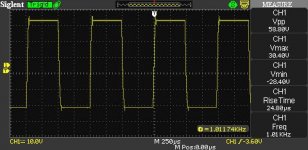
2) RS on square waves is from 1us to 1.2us all the way to 30Vpp
With 8 Ohm load.
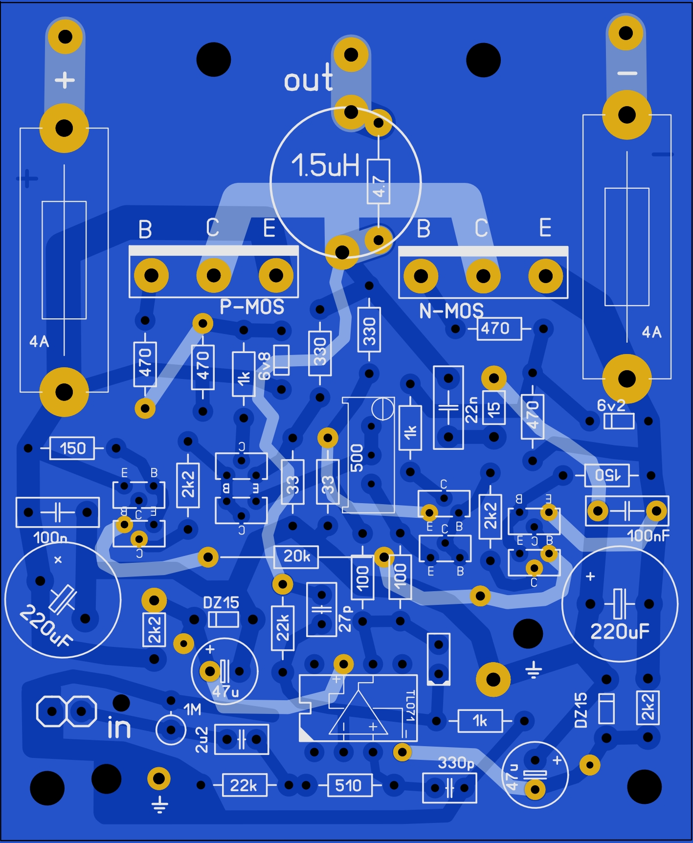
3) 1kHz sqare wave with load, after reaching 30Vpp, will look like on the attached pictures. It oscillates after reaching little bit over 30Vpp.
Perhaps this is too much for a square wave test? It's pretty harsh for the amp, I guess.
When it oscillates like this, amperage shown on my PSU is 3.5A.
No idea how it's possible, because this PSU shouldn't be able to deliver this amperage at 72V, it only has 180W, and my previous experience was that even this 180W is optimistic.
Square waves were tested with Zobel in place, it's a miracle how it survived... didn't even smell any smoke 🙂
4) A few times, it went into exactly same kind oscillation (as far as I can tell), after running for a while on sinus wave, and when (at the end of the test), I turned input V back to 0.
This behavior will have to test further tomorrow. I'm kind of not worried about square waves oscillation, but this is more
worrisome...
I forgot I left 'custom current limiter' set to 0.5A on my lab PSU 🙂
The amp was starving for current. Silly me...
1) So, now sinus waves look perfect, clipping happens at 70Vpp,
upper sinus wave. With 8Ohm load.
2) RS on square waves is from 1us to 1.2us all the way to 30Vpp
With 8 Ohm load.
3) 1kHz sqare wave with load, after reaching 30Vpp, will look like on the attached pictures. It oscillates after reaching little bit over 30Vpp.
Perhaps this is too much for a square wave test? It's pretty harsh for the amp, I guess.
When it oscillates like this, amperage shown on my PSU is 3.5A.
No idea how it's possible, because this PSU shouldn't be able to deliver this amperage at 72V, it only has 180W, and my previous experience was that even this 180W is optimistic.
Square waves were tested with Zobel in place, it's a miracle how it survived... didn't even smell any smoke 🙂
4) A few times, it went into exactly same kind oscillation (as far as I can tell), after running for a while on sinus wave, and when (at the end of the test), I turned input V back to 0.
This behavior will have to test further tomorrow. I'm kind of not worried about square waves oscillation, but this is more
worrisome...
Attachments
Last edited:
The time-constant is only 10ns, it is too short to have a beneficial effect.I tried Zobels (47 Ohm + 220pF) between DG, but this triggered immediate oscillations.
Try 470 ohm + 2n2 instead
In most amplifiers, the zobel is absolutely not optional, it is essential for the stability.I can try more aggressive Zobel, but I think that's not the point.
There shouldn't be any oscillations, Zobel or not.
It's only for emergencies, right?
Build any chipamp without one, and it is sure to oscillate.
With your topology, the zobel is even more important.
If the oscillation frequency is around 270kHz, it probably indicates a global stability issueSquare waves were tested with Zobel in place, it's a miracle how it survived... didn't even smell any smoke 🙂
4) A few times, it went into exactly same kind oscillation (as far as I can tell), after running for a while on sinus wave, and when (at the end of the test), I turned input V back to 0.
This behavior will have to test further tomorrow. I'm kind of not worried about square waves oscillation, but this is more
worrisome...
Minek! Try to remove P14, P17 🙂
Another correction may be required.
Limit the current to 0.5A when checking 🙂
Another correction may be required.
Limit the current to 0.5A when checking 🙂
>Minek! Try to remove P14, P17 🙂
If I remove R14/R17 the sim shows huge oscillations.
Perhaps Ian can tell, but I think these resistors are integral part of this topology...
Since it's less technically invasive, in the next step, will try Elvee's Zobels (470 Ohm + 2n2)
If I remove R14/R17 the sim shows huge oscillations.
Perhaps Ian can tell, but I think these resistors are integral part of this topology...
Since it's less technically invasive, in the next step, will try Elvee's Zobels (470 Ohm + 2n2)
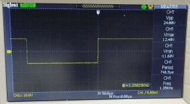
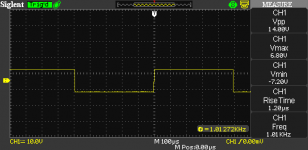
Latest test results with Elvee's Zobels (470 + 2n2) between D-G.
Everything tested with 8 Ohm resistive load.
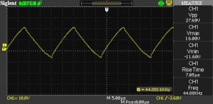
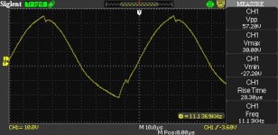
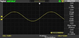
1) Sinus waves in all kind of ranges look more or less fine
2) Previous kind of 240kHz oscillations is gone.
3) Square waves go without oscillations up to 60Vpp
4) There is overshot on the square, getting relatively smaller as Vpp go higher
5) RS is slower than before (1.2us): 1.6us now, and 24us when square Vpp is 58V.
Previously, 1.2us was consistent with the slew rate of TL071.
6) This triangle wave in one of the photos, is actually a sinus at 44kHz / 27Vpp
So I guess it is an improvement.
Not sure about RS numbers increase, how these compare to other real-life amps?
Everything tested with 8 Ohm resistive load.
1) Sinus waves in all kind of ranges look more or less fine
2) Previous kind of 240kHz oscillations is gone.
3) Square waves go without oscillations up to 60Vpp
4) There is overshot on the square, getting relatively smaller as Vpp go higher
5) RS is slower than before (1.2us): 1.6us now, and 24us when square Vpp is 58V.
Previously, 1.2us was consistent with the slew rate of TL071.
6) This triangle wave in one of the photos, is actually a sinus at 44kHz / 27Vpp
So I guess it is an improvement.
Not sure about RS numbers increase, how these compare to other real-life amps?
Attachments


Last edited:
The 470/2n2 local FB network is just a starting point for further iterations: it is obviously much too aggressive, but it is stable.
You can now try other values: for example, try to reduce C in a E6 progression (2n2, 1n5, 1n0, ...)whilst adapting R to improve the square response/keep things stable.
At the same time, you can tweak the other caps in the amp, to improve matters.
A SR of 30V/1.6µs is 19V/µs, slow enough to make many members cringe in disgust, but more than sufficient in practice.
If it can be improved to exceed 30V/µs, it would be better, but it is not essential
- Home
- Amplifiers
- Solid State
- Square Law Amp