Thanks Elvee!
So this oversimplification is correct?
So this oversimplification is correct?
'R' value controls SR, and 'C' limits the oscillations
It's not just T constant R*C that matters, regardless of actual 'R' and 'C' values?
>A SR of 30V/1.6µs is 19V/µs, slow enough to make many members cringe in disgust
That's not good... We don't want this to happen 🙂
What my neighbors gonna say?
That's not good... We don't want this to happen 🙂
What my neighbors gonna say?
Things are less clear-cut: R determines the ultimate local gain at high frequencies, and the RC product the inflexion frequency where high frequencies begin.Thanks Elvee!
So this oversimplification is correct?'R' value controls SR, and 'C' limits the oscillationsIt's not just T constant R*C that matters, regardless of actual 'R' and 'C' values?
Below that inflexion, the effect will be mostly capacitive and will have some impact on the SR. Beyond, mainly the gain will be affected.
I tried 4 combinations so far. This is a lot of work (soldering/desoldering), because I'm working with pcb installed on chassis/heatsink..
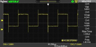
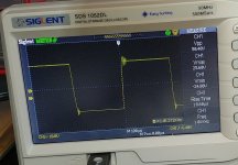
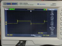
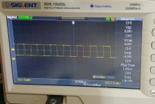
Here are results for 390 Ohm + 1n5 (load 8 Ohm).
Here are results for 390 Ohm + 1n5 (load 8 Ohm).
Attachments
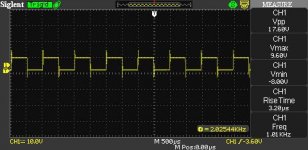
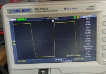
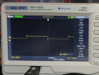
These are results for 270 Ohm + 1n5.
I also tried 270 Ohm + 1n, but amp was unstable and oscillating even without signal.
Taking photos with camera is much faster than using oscilloscope 'save screen' function.
Saving screen to usb takes 20s !!!
Looks like can't go lower with the 'C'. Perhaps should try lower R with 1n5 ?
Also - output Zobel is now 10 Ohm + 220nF for all today's tests.
Rails are 38V.
Attachments

Last edited:
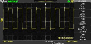
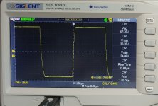
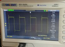
One more: 470 Ohm + 1n5
Higher R = Slower RS
This one looks the best to me, except for RS.
Higher R = Slower RS
This one looks the best to me, except for RS.
Attachments

What I generally do in such a case is to install female socket strips instead of the critical components: you can then swap them easily and quicklyI tried 4 combinations so far. This is a lot of work (soldering/desoldering), because I'm working with pcb installed on chassis/heatsink.
Ideally, each time you change the cap value, you should also adjust the R value, because the RC product has changedLooks like can't go lower with the 'C'. Perhaps should try lower R with 1n5 ?
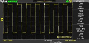
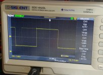
The ringing on the edges is not really acceptable. It should be reduced to a mere overshoot.One more: 470 Ohm + 1n5
Higher R = Slower RS
This one looks the best to me, except for RS.
Some other ideas: bypass R1 and R23 with 4n7 caps, to eliminate the parasitic pole they generate;
install your RC networks across R14 and R17 instead of D-G: it will include the driver in the compensation.
You could also try to compensate U1 with a light RC network
Elvee, if you were here, I would buy you beer for the whole month 🙂
Let me know if you ever come to NY..
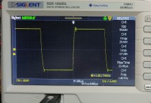
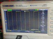
Did exactly what you said, and here are the results.
RC is 270 + 1n5.
Huge improvement.
Even slew rate is acceptable (but barely..).
Let me know if you ever come to NY..
Did exactly what you said, and here are the results.
RC is 270 + 1n5.
Huge improvement.
Even slew rate is acceptable (but barely..).
Attachments


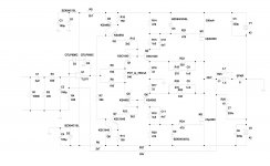
This is the latest schematic so far.
The numbering of all parts has been changed (compared with previous schematics), previously the numbers were kind of random...
Done testing for today. Tomorrow will test with unregulated PSU, speakers and music.
This amp has been tortured with square waves for the whole day.
I have to say, based on my history with square waves and amps, it is VERY robust 🙂
Attachments
Last edited:
Good, it begins to look the part. An additional tweak here and there to polish the work, and you are done 
Amp's been playing music for 2 hours now.
Everything is stable, and seems to be perfect.
Sounds very good, and it has very powerful bass, more than
any of my previous amps.
Fan controller is set to keep chassis temperature of 35 C.
Small transistors are running at 55 C.
Op-amps at 42 C
Rails 38V (idle current at 38V is 270 mA, it was originally set to 330 mA at 42V rails).
Detailed photo shows how RC network has been added on top of existing 330 Ohm resistors on on the pcb.
Additional 4n7 caps are soldered under the board.
Attachments


Last edited:
I'm wondering, perhaps with RC networks added,
the gate stoppers can be lower in value (100 Ohm)?
Would this speed up SR?
the gate stoppers can be lower in value (100 Ohm)?
Would this speed up SR?
You could try that just solder 150R parallel to 330R gate resistors, but check again for overshoot...
Btw interesting design!
Cheers.
Btw interesting design!
Cheers.
Without the 4n7, you could dispense completely with the stoppers.I'm wondering, perhaps with RC networks added,
the gate stoppers can be lower in value (100 Ohm)?
Would this speed up SR?
With the caps, it depends on the layout: if it is OK, you can eliminate them, and it will be (slightly) beneficial.
Otherwise, you may need to keep them, but the effect will be much lower than the 2K2 you bypassed.
I remember Ian emphasizing several times, that gate stoppers were really required, and with unusually high value (470 Ohm).
Supposedly it was because of HF stability.
So I'm suspecting some oscillations in the past, have been solved by
increasing gate stoppers values (slowing down the mosfets).
OP devices are driven from low impedance sources here, so normally they should not require 470 Ohm stoppers. Am I right?
Supposedly it was because of HF stability.
So I'm suspecting some oscillations in the past, have been solved by
increasing gate stoppers values (slowing down the mosfets).
OP devices are driven from low impedance sources here, so normally they should not require 470 Ohm stoppers. Am I right?
Stoppers are generally required to damp a low-impedance path, part of a potential VHF oscillator.OP devices are driven from low impedance sources here, so normally they should not require 470 Ohm stoppers. Am I right?
In your case, everything is more or less high impedance, even with the 4n7.
There are small caps to the ground all along the path though, and they create parasitic poles.
They might also be sufficient to create oscillations.
If the drivers collectors are directly tied (in AC) to the gates of the MOS, instabilities could appear.
Normally, a low-value resistor should be sufficient to kill the oscillations, without impacting the response; 47ohm for example
Hi Minek, Elvee,
That was a great effort! It's not an easy beast to tame. One area to yet to consider is the zeners across the opamp; their capacitance is quite large reducing slew rate and capacitance changes with opamp output voltage creating unwanted distortion at 20kHz and making it harder to stabilize. Attached is a jig that plots the capacitance for two 6.8V 1W zeners in series. The capacitance is 286pF at 0V rising to a peak of 561pF at 0.45V then flattening to 430pF above 4V (then the breakdown current starts).
What to do? One option is to omit the zeners and use a 33pF capacitor across the opamp. This will increase the slew rate by about a factor of 10 (then 100 ohm gate stoppers seem to be optimum). Another option is to use clamping diodes in series with the zeners and then biasing the zeners with a few uA (with a 10Meg from the 15 volt rails).
The attached circuit uses clamping diodes with biased zeners improving the slew rate by about 10 times compared to the ordinary zener arrangement. Distortion at 20kHz is reduced by a factor of 6 times. All the best. I hope this helps.
BTW I discovered the zener clamp method today in an ON Semi application note that was linked on Susan Parkers thread Post 1680 Zero Feedback Impedance Amplifiers and the link: Zener Theory and Design Considerations Handbook (see Fig 30 on p28)
Attachments
Last edited:
Back with another iteration. This time I reduced the gate-source resistors (R10,R20) to 220 ohms (was 470R). Then add LEDs to get 4V gate bias voltage without increasing current in the driver stage. C7 across the opamp can probably be removed and 50 ohm gate stoppers.
It gives about twice the slew rate of my previous. Now more like 20-30V/us. THD is pretty low at 1W and 20kHz. Nice if your build can get closer to these sim figs🙂.
It gives about twice the slew rate of my previous. Now more like 20-30V/us. THD is pretty low at 1W and 20kHz. Nice if your build can get closer to these sim figs🙂.
Attachments
very interesting!
I will have to have a play with this. I suspect a practical situation requires simulating mismatched power devices too, because no source resistors also means unbalanced power sharing.
Why didn’t somebody try this no rs approach already ?
Les Sage did it back in the late 80's with his Superamp / Supermos modules. He wildly exaggerated their spec's but they did sound good. Better than anything else I could get my hands on at the time..
- Home
- Amplifiers
- Solid State
- Square Law Amp