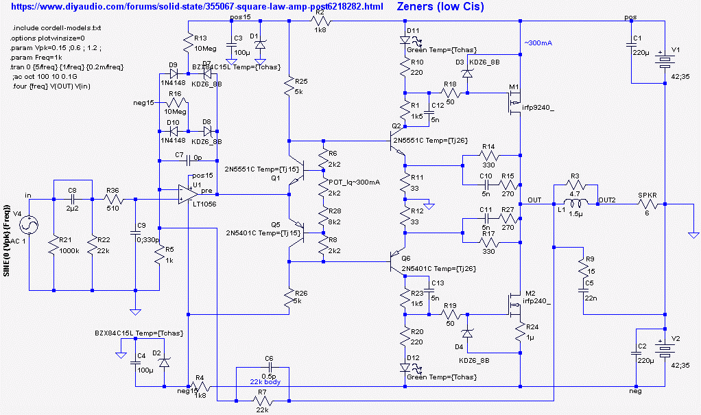
Back with another iteration. This time I reduced the gate-source resistors (R10,R20) to 220 ohms (was 470R). Then add LEDs to get 4V gate bias voltage without increasing current in the driver stage. C7 across the opamp can probably be removed and 50 ohm gate stoppers.
Ian, I'm simming this at 42V rails (that's my PSU).
My latest "as built" .asc attached. Zeners used instead of LEDs.
Q2/Q6 are running at 300mW - that's too much for small transistor.
In my prototype R1 (from your .asc) is at 1k5 (plus parallel capacitor).
We need to lower current consumption at Q2/Q6....
Attachments
Last edited:
Hi Minek,
I have changed to 42V rails and 1k5 resistors plus parallel caps. 300mW for TO-92's is near their limit but my amps had them tightly strapped to the bias transistor with heatshrink which provided enough cooling.
Simulating your amp from start to warmed up is tricky because of the fan controller. Normally without a fan controller the bias sensor (Vbe multiplier) senses the changing heatsink temperature to try and keep the idle current fairly constant. But when you have a fan controller regulating the heatsink you cant use the heatsink for feedback in the same way as normal.
Despite this you seem to have achieved a slight reduction in idle current after warming up which makes it safe. That is fortunate.
But how do we simulate/design for safe thermal biasing with a fan controlling the heatsink temperature? This fan controller biasing situation is not covered in Bob Cordell's or Douglas Self's design books that I am aware of. It's new territory
Attached are 3 simulation files for different ways to achieve fairly stable biasing by design. The first "1d" uses the current source transistors (Q4,8) for sensing the heatsink temperature as well as the biasing transistor/diodes (Q1,5). These need to sense some of the higher power transistor case temperature for enough thermal feedback. Kf is the attenuation factor for sensing the drop from the junction to the heatsink and in this simulation Kf needs to be 60% for the idle current to stay at about 300mA from cold to warmed up.
The second sim "2d" does not use the current source transistors (Q4,8), instead 4 biasing transistor/diodes are used (Q1,5,9,10) and the idle current is trimmed by injecting a few mA into the emitter resistors, and BAT54 diodes are added to the emitters of Q2,6. Then the bias transistors are coupled to Q2 and Q6 using a wraparound metal clamp (so thermal coupling factor is around Kf~0.9). This can get the idle current almost constant from start to warmed up while the fan keeps the base plate temperature at a fixed final temperature (I used 35C).
The third sim "1e" also doesn't use the ccs nor BAT52 diodes, instead Q2,6 are cascoded (with Q9,10) and only two bias transistor diodes (Q1,5) which are fairly tightly thermally coupled to the cascode transistors (coupling factor is Kf). The cascode inner transistors (Q2,6) run at the PCB temperature which in this amp is very close to the chassis temperature. With Kf=0.7 the idle current warmed up is about the same as starting current.
The second and third sims are more practical than the first by sensing the driver transistors temperature rather than the power transistors. The first is harder to get the right amount of thermal coupling to the power transistors.
Now, if we used a standard naturally ventilated heatsink then any of these 3 methods will work OK; but the equations I have used will need to be changed to allow for a "free" to vary non-controlled heatsink temperature, which is 'Tchas' in my equations.
I hope this is not too confusing, making something simple look so... complicated😱. Oh well, it was nice to have something so different to think about🙂.
Attachments
Another bias method "3d" similar to "2d" but now without BAT54's. Simpler.
The Vbe multiplier with two transistors tied thermally to the driver transistors (which are warmed to the chassis temp and beyond by their dissipation. The temp-co can therefore be tweaked by the value of the driver collector resistors😎. In this sim the idle current at start is 300mA and 315mA warmed up.
BTW "Temp=<values>" for these devices are given in the attached zip. They assume the fan controller regulates the chassis temperature at 35C irrespective of the MOSFET dissipation. That's why the Vbe multiplier cannot be mounted on the heatsink (chassis) - it would not see any temperature changes😱. So the darn thing can't do it's job when the fan is regulating the chassis temperature.
The only viable alternative that I can see is to sense the driver transistors temperature changes, which roughly correlate with the power MOSFETs junction temperatures, at least at idle.
If anyone else has any bright ideas on this tricky problem when the fan controller sets the heatsink (chassis) temperature, then we'd love to hear from you.
Attachments
Last edited:
Question:
Bias voltage needs to be modified when output transistors:
a) change temperature (and this is not gonna happen with constant
temperature maintained by the fan),
OR
b) change current
?
Or perhaps there are some other, mysterious reasons WHY bias change is needed?
In a) case - I don't see any problems. Temp didn't change, so no need to
change bias
In b) case - instead of sensing temperature, we need to sense current.
Your amp is obviously stable as built with the fan controller operating so there is no need to change anything....?
Or perhaps there are some other, mysterious reasons WHY bias change is needed?....
A few posts back I said this is a tricky design problem. If someone wanted to make this amp like your one they may not get theirs stable since the thermal issues are so 'hit-and-miss' -- meaning unpredictable.
Since I had some part in the original square-law amp design 25 years back I would like to see a vertical MOSFET version like yours work at least as good as the first lateral MOSFET one.
Please bear with me while trying to find the best way to do it using simulations.
I don't expect you to modify your design to my changes.
But anyone wanting to make another like this could learn from your build and improve on some things, like the blocking diodes for low capacitance for faster slew rate and lower distortion at 20kHz in Post 97.
In my build, even though I use temp controlled fan,
transistors Q4/Q8 (schematic from post #89) are placed on the heatsink,
and I've done testing of bias adjustments with fan turned off, and heatsink temperature controlled
by little external fan, that I can easily turn off/on, and make it run hotter.
These transistors were sensing temperature and lowering bias very nicely and quickly.
I guess more rigorous testing would be needed to find out, if correct amount of bias was getting adjusted (actual compensation).
I think I still will try to improve slew rate - perhaps with simple capacitor in place of diodes, and lowering the gate stoppers, but I think I'll do another build later on.
I still have PCBs, and buckets of parts 🙂