If all you require is a passive series coil, then just add the series inductance value to the driver Le. That way, you can still use the loudspeaker wizard to include filling.
Awesome, thanks for this hint.
Now i also want to incooperate the dcr of the coil, which will affect Qts via Qes to my understanding. Is it as easy as described here HiFi Loudspeaker Design ? Or does the series resistance also has other effects, besides loss of efficiency?
Now i also want to incooperate the dcr of the coil,
Would i also have to add the added series resistor to the woofer-Re in Hornresp, besides the changed Qes? I guess so, as i can't use the passive filter as i workaround it(coil-Le + woffer-Le) to have also the filling calculated.
Would i also have to add the added series resistor to the woofer-Re in Hornresp, besides the changed Qes?
The series coil resistance can be added to either Rg or Re. If added to Re, it will automatically change the value of Qes and therefore also Qts. You don't have to manually change the values of Qes or Qts yourself. If added to Rg, the resistance will be external to the driver, and therefore will not change the driver Qes or Qts values.
Now that I'm in the asking mode, Multiple entry horns get into this wonderful explanatory mix??
Hi Mark,
A system model acoustic circuit diagram option will be included in the multiple entry horn loudspeaker wizard in the next update. System models for every other possible Hornresp loudspeaker configuration are also now being developed. Although requiring a massive amount of work, once I got started I just couldn't stop... 🙂.
I hope to be in a position to release an update in the next week or so.
Kind regards,
David
Only a little obsessive compulsive. Why is it so many of us on this thread have that blessing, er curse.....
This will be an awesome addition. I'm training someone on Hornresp now. And it will greatly aid that. Also help me a bit because I'm not used to doing bandpass designs and the flow chart really helps think it through.
Thanks David.
Further question.
I'm designing a short horn Ahem waveguide for a dome tweeter and I'm looking to see the effects of the horn only. We used to do this with an eg of 0 volts. Doesn't seem to work anymore. I missed something in all these updates I am sure. So many features I don't use often or keep track of.
So how do I find the horn effects only now Master McBean ?
Hi Mark,
You can drive your Sd with a constant acceleration 😉
(Double click Eg twice)
Thanks for all the support so far.
Haven´t had the time to deep dive into Hornresp just yet. Although from what I understand filling/damping can only be added to the wizard if i have only one single pipe/section.
So if i have like in my case a chamber with the driver, a tapered pipe, a straight section and lastly a tapered section with a vent i will not b able to see how different filling will affect the output/graphs/SPL?
David, I needed to read the manual (to understand more) so i downloaded it to my computer and imported into MS Word and are about to make it fit more on a standard "office size paper". Maybe i will paste some screen shots to it too. It will be a piece of work but easier for me (and others) as a newbie to this. Hope it is ok?
So if i have like in my case a chamber with the driver, a tapered pipe, a straight section and lastly a tapered section with a vent i will not b able to see how different filling will affect the output/graphs/SPL?
Hi Sharky,
If you're in the input parameters section in edit mode, go to tools, then loudspeaker widzard.
Then in the second dropdown menu you can select filling 😉
Hi Mark,
The development version is working well - I think you are going to like it... 🙂.
The functionality was changed in April 2019 to also include a constant acceleration option. See the post linked below for details.
https://www.diyaudio.com/forums/subwoofers/119854-hornresp-939.html#post5757317
Use the constant velocity (Vel) option.
Kind regards,
David
This will be an awesome addition.
The development version is working well - I think you are going to like it... 🙂.
We used to do this with an eg of 0 volts. Doesn't seem to work anymore.
The functionality was changed in April 2019 to also include a constant acceleration option. See the post linked below for details.
https://www.diyaudio.com/forums/subwoofers/119854-hornresp-939.html#post5757317
So how do I find the horn effects only now Master McBean ?
Use the constant velocity (Vel) option.
Kind regards,
David
Hi Sharkythefrog,
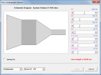
Filling can be added to multiple segments.
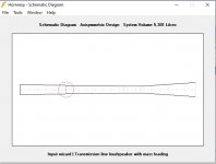
Absorbent filling material can be added to those parts of the system specified using horn segments, as shown in the attached example.
Not a problem.
Kind regards,
David
Although from what I understand filling/damping can only be added to the wizard if i have only one single pipe/section.
Filling can be added to multiple segments.
So if i have like in my case a chamber with the driver, a tapered pipe, a straight section and lastly a tapered section with a vent i will not b able to see how different filling will affect the output/graphs/SPL?
Absorbent filling material can be added to those parts of the system specified using horn segments, as shown in the attached example.
Hope it is ok?
Not a problem.
Kind regards,
David
Attachments
Well,
I ran in to at least two problems even before that (and after reading the manual and quite a few posts here).
1) It should be possible to set S2 in the first part of the pipe and then set S2 to another value in the next section of the pipe. But as soon S2 is changed at the second part, it also changes in the first part.
2) The calculations for the volume is ten times wrong. It says 1,6 litres but should be 16 litres. The software is asking for cm everywhere but are actually calculating somewhere as if it was mm inserted.
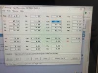
Are you sure about the units? Can you post a screenshot with the input?
Shure.
Look at the explanatory text at the bottom of each picture, while pointing at the blue field.
Running into more problem than this:
Cant find MMd for my driver, only Mms
Cant find Voice coil Lenght, but Height for my driver. I guess they mean the dame.
Attachments
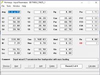
BI i said to be Tesla.m but doesnt work. Get the error message "Cant be lower than 0,01". Seem to ask for tesla.mm.
When I enter your numbers, I get 18,31 l volume.
Press CTRL+U when in the Sd window and enter the parameters there, it will calculate the parameters from the common ones.
Press CTRL+U when in the Sd window and enter the parameters there, it will calculate the parameters from the common ones.
This is getting more and more intersting. 🙂
Rms in HR is asked for as "Newton.sec/m" while Rms in the drivers specs are set to kg/s
Why does it ask for "Closed rear chamber..." as I dont have one?
I tried to figure out what all these are but couldnt find an explanation: Vrc, Ap, Vtc, Lrc, Lpt, Atc. They all refers to "Rear chamber" of "Throat chamber". What is exactly a "chamber" in this case. As I have four "chambers" in the design, THe chamber behind the drivers (cylindrical(, the next "chamber" (tapered/conical pipe), the third "chamber" (cylindrical pipe) and the last (tapered/conical pipe) with the vent (probably here refered to as the "port"). The manual doesnt give any clues - at least not to me 🙂
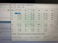
Thats because i have entered the length in mm not cm. But this might be wrong for other calculation purposes. Is it the circular area or the length that is used in the sotfware as mm, I dont know. See also the enclosed picture.When I enter your numbers, I get 18,31 l volume.
This sets the BI to a totally different value than calculating it from the driver specs where 16mm = 0,0016m x 0,93T = 0,001488 Tesla.m (as explained i the help text of the field)Press CTRL+U when in the Sd window and enter the parameters there, it will calculate the parameters from the common ones.
Attachments

This is still a mystery. I remember doing this with my first try and then it worked, so something has changed in the set up. Trying to find out what.Well,
1) It should be possible to set S2 in the first part of the pipe and then set S2 to another value in the next section of the pipe. But as soon S2 is changed at the second part, it also changes in the first part.
- Home
- Loudspeakers
- Subwoofers
- Hornresp