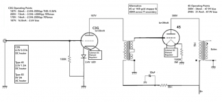
In this schematic the 45 has AC heating but I Use a DC regulator now .
I plan on using DC for the 45 and will try the C3G with AC. If the C3G needs DC, then I can alter later.
You are running the C3G in triode using both grids. Have you tried using only 1 grid? Differences?
Also, are the 30K and 1K resistors necessary or an alternative approach whereby either design is valid?
If output tube not tend to oscillate, the 1k gridstopper can be omitted.
Most of interstages has a bump at higher frequencies. The proper load at the secondary reduces and eliminates its. Without it, the frequency boost "helps" pushing the output transformer upper bandwidth higher, but IMHO it unnecessary frequency correction.
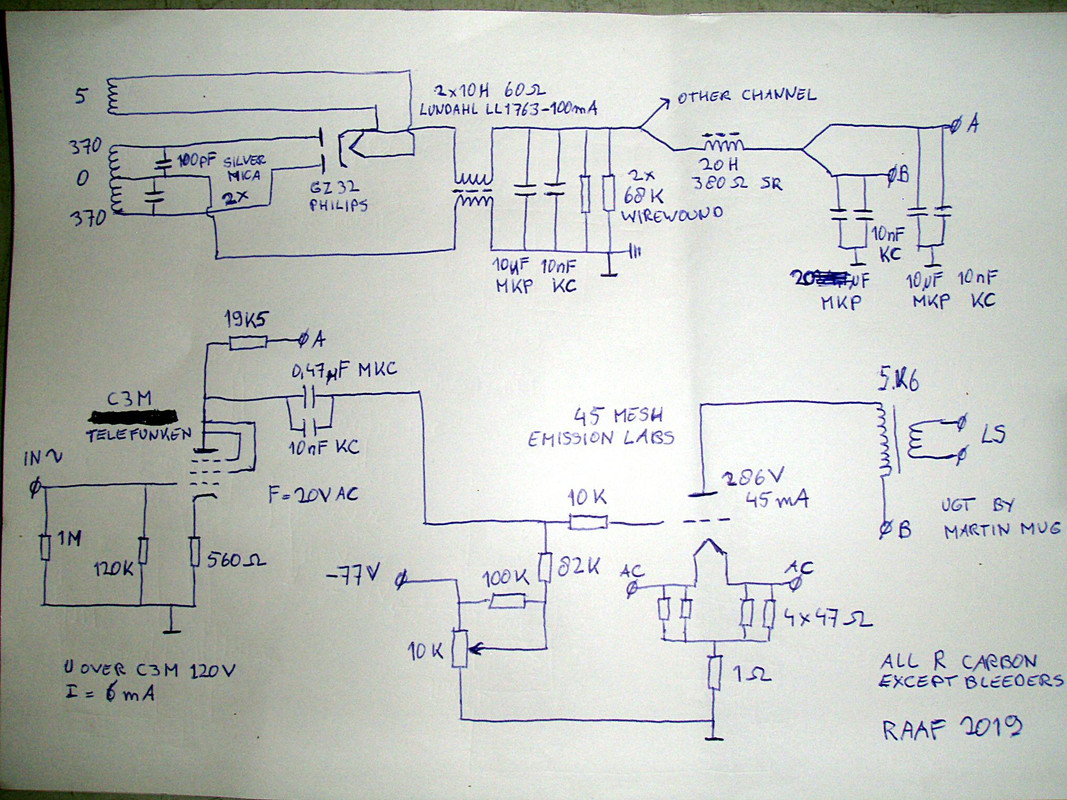
Some observations about the schematic in Post # 18 and Post # 21
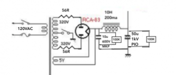
1. The use of a dual 10 Henry Common Mode Choke:
Causes all of the wiring of the Power transformer: Primary, B+ secondary, and 5V rectifier filament secondary, to Radiate large Hum and Noise Voltages into the air (just like a Radio Transmitter. They are all floating, versus all the other wiring of the amplifier.
You will likely get hum and noise introduced into the rest of the amplifier circuitry.
The solution: get rid of that Common Mode Choke.
And, the Common Mode Choke does Not reduce the B+ ripple voltage.
So, it does not really perform a useful function, unless you have extremely large noise voltages on your Power Mains.
In the case of extremely large noise on the Power Mains, use a special filter that is driving a power strip (and all of the special filter, and all of the power strip has to be Outside of the amplifier metal enclosure).
2. The B+ ~A capacitor pair, and B+ ~B capacitor pair, filter are directly wired together.
Instead, there should be a resistor between the ~A and ~B filter capacitors, so that the output stage B+ and the input stage B+ are not connected together. The resistor will do two things:
First isolate the input tube stage B+ and the output tube stage B+;
Second, the resistor will reduce the ripple of the input tube stage’s B+ (the input stage is more sensitive, so a little bit of B+ ripple is more of a problem there, you need lower the ripple there.
The C3G is in triode wired mode.
If there is not enough gain to fully drive the 45 Grid, then you can use a Bypass Capacitor across the 560 Ohm cathode resistor to increase the gain.
3. Some 45 data sheets specify 100k maximum grid resistor if you use fixed bias.
The total series resistance of the schematic is about 100k.
If you use the Emission Labs 45, check to see what Emission Labs recommends for the maximum grid resistance in fixed bias mode.
4. You need to ground one end of the output transformer secondary.
Safety First!
(Prevent the Surviving Spouse Syndrome).
OK, I admit, there are some who say that an ungrounded secondary sounds better.
I bet if the circuit is good, and also if the output transformer is good, grounding it, or not,will not make it sound any different.
Get a friend, and do a blindfold test of that sound, grounded, and ungrounded.
One is blindfolded, and the other connects, disconnects, connects, disconnects, from ground, in no particular order.
Then, swap places with your friend, and repeat the test.
Now, after you both did the blindfold test, you can talk about it.
Last edited:
Here is the latest version of the schematic based upon your input. I have a few follow up questions:
1. currently thinking of using Filament Bias on the 45 output tube. This is in line with Thomas Mayer's comments "Filament bias utilizes the filament current in addition to the plate current to generate the bias voltage through a cathode resistor which now can be much smaller." Thoughts on this approach? If this does not work, then would go with Ultrapath approach to keep the cathode capacitor out of the signal path.
2. Is the 30uF cap from B+ to the interstage transformer in the signal path? I was hoping to use an electrolytic if the 30uF cap is NOT in the signal path. But if it is in the signal path, then a PIO would be appropriate.
3. Eliminated the 1K grid stopper (45 tube). If the 45 tube has oscillation, then the grid stopper will be put back in.
4. Eliminated the 30K resistor across the secondary of the IT. Don't foresee high frequency bump. The IT is flat out to 100Khz.
Attachments
1. Filament bias:
Your filament supply will have to do a lot of work and it will get pretty warm in the summer. On the upside, you might not find the need to start up the fireplace in the winter.
Look, the top of your cathode resistor needs to bias up to around +40V right? (according to your schematic). Your filament draws 1.5 Amps, right?
So the cathode resistor would be a very modest 26-27 ohms BUT it will need to dissipate 60 Watts of energy as heat. Wow... The transformer winding will have to deliver (rectified, filtered, etc.) um.... 1.5 Amps to 42.5 Volts... That's like 63 Watts.. Probably has to be a 50VAC 100Watt transformer (for each channel). yeah.. not so nice.
2. Ultrapath. Right. I do it. So do some others here. If your power supply is super quiet, it can work well. But last time I looked you only have one choke. Look into building a maita regulator perhaps after the choke. Maybe you could rig up a really robust cap-multiplier that could handle the required current draw (I think that would be NICE too) to put after that choke. Since you are doing monoblocks this would be a nice way to go it... Or string a few more chokes and caps...
2a. If your power supply is not super quiet, then you could look at the 1928 schematic of Loftin-White. The earliest versions of their amplifier used a noise cancellation network. I can testify that this kind of noise cancellation works rather nicely. But it needs to be tuned a bit for the input/driver tube. Still, it can work. But you might want to look into a regulator instead. Or just use a cathode by-pass cap like 90% of the folks out there who go for cathode bias.
2b. You might consider fixed bias instead of cathode bias. Maybe you do not have a winding for this. But you could rig up a separate negative supply for this. It's just an idea. I would seriously consider it with an IT, then ditch the input cap to get your B+ down to around 260V. Then your C3g might have a chance of survival too.
3. Your amplifier is single-ended. ALL the components are in the "signal path". These days I am going no-compromise all film caps for my single ended amps. Films are so much cheaper and are of excellent quality today. There are a lot of good choices for Film caps too. If you have some space, then go for film caps. You mentioned Thomas Mayer - those ASC X386s caps he uses are great. If space is a concern, look towards DC-Link caps. Don't pretend they are not in the signal path.
4. Absolutely nothing wrong with a 1k grid stopper on a 45 tube. Sure, if you can do without it, then do that. Having funny RF (or whatever) sounds on one of your vintage or china 45's ? put in the grid stopper in is the quickest solution. Bet you can't hear it if it is a plain nice (cheap) metal film. It needs to go close to the 45 pin though.
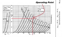
5. Do you already own some C3g's ? Hope they are old and beat up, because you are running them hot. I would hate to see you burn through NOS ones. Look at the Siemens triode curves from the datasheet please.
Your filament supply will have to do a lot of work and it will get pretty warm in the summer. On the upside, you might not find the need to start up the fireplace in the winter.
Look, the top of your cathode resistor needs to bias up to around +40V right? (according to your schematic). Your filament draws 1.5 Amps, right?
So the cathode resistor would be a very modest 26-27 ohms BUT it will need to dissipate 60 Watts of energy as heat. Wow... The transformer winding will have to deliver (rectified, filtered, etc.) um.... 1.5 Amps to 42.5 Volts... That's like 63 Watts.. Probably has to be a 50VAC 100Watt transformer (for each channel). yeah.. not so nice.
2. Ultrapath. Right. I do it. So do some others here. If your power supply is super quiet, it can work well. But last time I looked you only have one choke. Look into building a maita regulator perhaps after the choke. Maybe you could rig up a really robust cap-multiplier that could handle the required current draw (I think that would be NICE too) to put after that choke. Since you are doing monoblocks this would be a nice way to go it... Or string a few more chokes and caps...
2a. If your power supply is not super quiet, then you could look at the 1928 schematic of Loftin-White. The earliest versions of their amplifier used a noise cancellation network. I can testify that this kind of noise cancellation works rather nicely. But it needs to be tuned a bit for the input/driver tube. Still, it can work. But you might want to look into a regulator instead. Or just use a cathode by-pass cap like 90% of the folks out there who go for cathode bias.
2b. You might consider fixed bias instead of cathode bias. Maybe you do not have a winding for this. But you could rig up a separate negative supply for this. It's just an idea. I would seriously consider it with an IT, then ditch the input cap to get your B+ down to around 260V. Then your C3g might have a chance of survival too.
3. Your amplifier is single-ended. ALL the components are in the "signal path". These days I am going no-compromise all film caps for my single ended amps. Films are so much cheaper and are of excellent quality today. There are a lot of good choices for Film caps too. If you have some space, then go for film caps. You mentioned Thomas Mayer - those ASC X386s caps he uses are great. If space is a concern, look towards DC-Link caps. Don't pretend they are not in the signal path.
4. Absolutely nothing wrong with a 1k grid stopper on a 45 tube. Sure, if you can do without it, then do that. Having funny RF (or whatever) sounds on one of your vintage or china 45's ? put in the grid stopper in is the quickest solution. Bet you can't hear it if it is a plain nice (cheap) metal film. It needs to go close to the 45 pin though.
5. Do you already own some C3g's ? Hope they are old and beat up, because you are running them hot. I would hate to see you burn through NOS ones. Look at the Siemens triode curves from the datasheet please.
Attachments
Last edited:
I plan on using DC for the 45 and will try the C3G with AC. If the C3G needs DC, then I can alter later.
You are running the C3G in triode using both grids. Have you tried using only 1 grid? Differences?
The C3G probably doesn't need DC, the 45 definitively does.
I have tried 1 grid to anode and one to cathode but this is what I like most .
Also, why go for DC heaters on the 45? Rod's boards are Fantastic, but you could easily just start with AC heaters. Solve all the other problems, then consider going to DC.
AC heaters are pretty bulletproof and easy. I use AC and there is no hum on my 95db speakers. Hum will come from your power supply.
AC heaters are pretty bulletproof and easy. I use AC and there is no hum on my 95db speakers. Hum will come from your power supply.
The C3G probably doesn't need DC, the 45 definitively does.
I have tried 1 grid to anode and one to cathode but this is what I like most .
Nope. 45's do not need DC. They work very nicely with 2.5VAC will have almost no hum (ear right up against 95db speaker, ok you hear some hum). Same with 2a3's. The 300b is another story though.
Most (90%) of any hum will be from his single choke B+ supply.
Some observations about the schematic in Post # 18 and Post # 21
1. The use of a dual 10 Henry Common Mode Choke:
Causes all of the wiring of the Power transformer: Primary, B+ secondary, and 5V rectifier filament secondary, to Radiate large Hum and Noise Voltages into the air (just like a Radio Transmitter. They are all floating, versus all the other wiring of the amplifier.
You will likely get hum and noise introduced into the rest of the amplifier circuitry.
The solution: get rid of that Common Mode Choke.
And, the Common Mode Choke does Not reduce the B+ ripple voltage.
So, it does not really perform a useful function, unless you have extremely large noise voltages on your Power Mains.
In the case of extremely large noise on the Power Mains, use a special filter that is driving a power strip (and all of the special filter, and all of the power strip has to be Outside of the amplifier metal enclosure).
2. The B+ ~A capacitor pair, and B+ ~B capacitor pair, filter are directly wired together.
Instead, there should be a resistor between the ~A and ~B filter capacitors, so that the output stage B+ and the input stage B+ are not connected together. The resistor will do two things:
First isolate the input tube stage B+ and the output tube stage B+;
Second, the resistor will reduce the ripple of the input tube stage’s B+ (the input stage is more sensitive, so a little bit of B+ ripple is more of a problem there, you need lower the ripple there.
The C3G is in triode wired mode.
If there is not enough gain to fully drive the 45 Grid, then you can use a Bypass Capacitor across the 560 Ohm cathode resistor to increase the gain.
3. Some 45 data sheets specify 100k maximum grid resistor if you use fixed bias.
The total series resistance of the schematic is about 100k.
If you use the Emission Labs 45, check to see what Emission Labs recommends for the maximum grid resistance in fixed bias mode.
4. You need to ground one end of the output transformer secondary.
Safety First!
(Prevent the Surviving Spouse Syndrome).
OK, I admit, there are some who say that an ungrounded secondary sounds better.
I bet if the circuit is good, and also if the output transformer is good, grounding it, or not,will not make it sound any different.
Get a friend, and do a blindfold test of that sound, grounded, and ungrounded.
One is blindfolded, and the other connects, disconnects, connects, disconnects, from ground, in no particular order.
Then, swap places with your friend, and repeat the test.
Now, after you both did the blindfold test, you can talk about it.
Most of the issues you mention have already been discussed in the thread about my amp.
45 SE amp
I however forgot to draw a 560 ohm resistor in the psu A + line and I spot another error : the 4 cathode resistors are 100 ohm each and not 47 ohm
Nope. 45's do not need DC. They work very nicely with 2.5VAC will have almost no hum (ear right up against 95db speaker, ok you hear some hum). Same with 2a3's. The 300b is another story though.
Most (90%) of any hum will be from his single choke B+ supply.
I changed from ac to dc on the 45 because of hum, on the speakers 97db it was acceptable, but annoying on the headphone
I changed from ac to dc on the 45 because of hum, on the speakers 97db it was acceptable, but annoying on the headphone
ok, that makes sense.
banpuku,
Your post #7 and #24 schematics are making some progress, good.
56 Ohm resistors, good.
Good, a 1500 Ohm self bias resistor for the 45. (be sure to bypass that resistor with a cap, because the output current goes through it); The 45 grid signal voltage versus the filament bias voltage is what makes that stage work.
That voltage will change unless you use a bypass cap.
Use a 100 uF @ 100V bypass cap there.
You are right! Changing the input cap from 10uF to 0.27uF will increase the ripple.
So make the B+ filter this way:
0.27uf, Choke, 100uF, 200 Ohm resistor, 100uF.
That is a small c, L, C, R, C filter (cLCRC).
The ripple will be OK again.
And, the B+ voltage will be near to ideal (may have to adjust the 0.27uF cap, might need 0.33uF, or 0.5 uF instead to get the B+ dead on.
Part of the capacitor uF value depends on whether you build 2 mono-block amps, or one stereo amp (2 times the current with a stereo amp, versus less current for a mono-block amp). And 2 times the current requires 2X the capacitance to get the same B+
Last edited:
There is a very old argument about AC versus DC on Directly Heated Triodes.
Too long to give all the reasons, all the measurement results, and all the theory behind,
so here are the conclusions:
DC filaments on DHT:
Gives less hum,
And more importantly, gives Less Intermodulation Distortion.
AC on DHT gives more hum, and gives more Intermodulation Distortion.
Too long to give all the reasons, all the measurement results, and all the theory behind,
so here are the conclusions:
DC filaments on DHT:
Gives less hum,
And more importantly, gives Less Intermodulation Distortion.
AC on DHT gives more hum, and gives more Intermodulation Distortion.
Last edited:
Yeah, probably a good idea.Or just use a cathode by-pass cap like 90% of the folks out there who go for cathode bias.
I plan on on using wima DC Link caps or Russian PIO caps (50uF, 1kV)If space is a concern, look towards DC-Link caps.
Back in it goes.Absolutely nothing wrong with a 1k grid stopper on a 45 tube.
I do not own any C3G tubes yet. I am open to other suggestions for the driver tube. If I stay with the C3G tube, one of the other operating points to consider is 170V : 14mA : -2.4Vk. If you have any other driver tubes (triode preferably) then please suggest with operating points. I am all ears.Do you already own some C3g's ?
Good stuff. Keep it coming.
I am open to other suggestions for the driver tube.
Some calculation:
In this operating point the #45 requires about 100Vpp grid swing in A1 region.
Let the driver stage capable swinging at least 20% greater than required grid swing: 120Vpp.
The "standard" 2V RMS input signal has 5.66Vpp.
Thus needed gain -at least- 21.2.
Each tube, which is has -as transformer loaded- greater gain than this, capable to drive this output tube.
If you already have interstage, its primary inductance limits the usable tubes:
Z= 2*pi*f*L (at f=20Hz)
2..3 * Ri < Z
You can use enough low internal -output- resistance tubes.
I continuously use trioded pentode tubes as VAS: D3a/E280F/E810F (in this order, or the last case E180F), C3g, to drive up to 150..200Vpp with low distortion.
I have 6S45P too, but its parameters show too much variance.
These tubes has enough low Ri: about 2-3k.
These tubes requires at least 50H choke/transformer load for enough low distortion, greater than this is better.
56 Ohm resistors, good.
You are right! Changing the input cap from 10uF to 0.27uF will increase the ripple.
So make the B+ filter this way:
0.27uf, Choke, 100uF, 200 Ohm resistor, 100uF.
That is a small c, L, C, R, C filter (cLCRC).
The ripple will be OK again.
Thanks, 6A3sUMMER. Appreciate the help. Is it common / best practice to put a resistor (like the 56ohm) between the power transformer and the rectifier? Or, is it better to adjust the voltage with the R in the cLCRC? Just curious.
Regarding the cLCRC. It's not too late to go with LCLC. I have purchased a nice 10H:120ohm PS choke, so I definitely will be using that. Otherwise, we can go with any PS design that works best. Thoughts on LCLC vs. cLCRC? Type 83 rectifier works with both C or L, but the data sheet says is prefers L. Power supply design is new territory for me, so any input is appreciated.
Some calculation:
In this operating point the #45 requires about 100Vpp grid swing in A1 region.
Let the driver stage capable swinging at least 20% greater than required grid swing: 120Vpp.
The "standard" 2V RMS input signal has 5.66Vpp.
Thus needed gain -at least- 21.2.
Each tube, which is has -as transformer loaded- greater gain than this, capable to drive this output tube.
If you already have interstage, its primary inductance limits the usable tubes:
Z= 2*pi*f*L (at f=20Hz)
2..3 * Ri < Z
You can use enough low internal -output- resistance tubes.
I continuously use trioded pentode tubes as VAS: D3a/E280F/E810F (in this order, or the last case E180F), C3g, to drive up to 150..200Vpp with low distortion.
I have 6S45P too, but its parameters show too much variance.
These tubes has enough low Ri: about 2-3k.
These tubes requires at least 50H choke/transformer load for enough low distortion, greater than this is better.
Thanks Euro21 for your help. Looking at the C3g tube, it does have a mu = 40. This exceeds the requirement of 21.1, so I believe we are good with regards to gain.
My interstage transformer has L = 75. This gives a Z = 9424. C3g Ri = 2,300 ohms. 3*2,300=6,900 which is less than Z, so I believe we are good here as well. Correct?
The E810F Ri = 42K. This would give 3*42,000 = 126,000 which is not less than Z, so this tube would not work. Am I thinking about this correctly?
YesMy interstage transformer has L = 75. .. so I believe we are good here as well. Correct?
No.The E810F Ri = 42K. ... Am I thinking about this correctly?
It's pentode Ri.
Calculated -trioded- Ri is 1140R.
Audio Asylum Thread Printer
E810F is very good tube, but at larger swing the 3th distortion factor starts to grow very soon. I use this tubes in phono amplifier (mV...V anode swing).
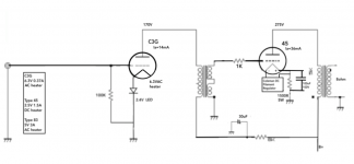
Here is the latest version of the schematics.
1. The power supply is currently a CLC, but I am strongly leaning towards an LCLC.
2. C3G operating points changed 170V : 14mA. Not sure if we have enough amps here, so any thoughts are encouraged.
3. 45 operating points changed to 275V : 36mA. This is in line with the maximums on the RCA 45 data sheet.
Attachments
There is a very old argument about AC versus DC on Directly Heated Triodes.
Too long to give all the reasons, all the measurement results, and all the theory behind,
so here are the conclusions:
DC filaments on DHT:
Gives less hum,
And more importantly, gives Less Intermodulation Distortion.
AC on DHT gives more hum, and gives more Intermodulation Distortion.
Forgot to mention that DC also burns out the filament faster... I have some nice old globe 45's - they only see AC on the filaments for exactly this reason.
Really no audible hum unless you are right up against the speaker. Even standing beside the speaker you can't hear the hum.
Intermodulation Distortion is real but is it truly audible? I have had guests listen to different amps, and nobody can tell which amp is AC or DC heater.
Both amps didn't "hum" enough. But my speakers are 95dB sensitivity. And we were also drinking wine 😉
Ian.
- Home
- Amplifiers
- Tubes / Valves
- C3G drives 45